Compressor housing of a radial compressor, and method for feeding charge air into an internal combustion engine

a compressor and compressor technology, applied in the field of compressor housing of radial compressor, can solve the problems of achieve the effect of minimizing efficiency loss of radial compressor and reducing flow loss

Pending Publication Date: 2022-05-05
TURBO SYST SWITZERLAND LTD
View PDF2 Cites 0 Cited by
  • Summary
  • Abstract
  • Description
  • Claims
  • Application Information

AI Technical Summary

Benefits of technology

[0006]Embodiments of the present disclosure provide a compressor housing of a radial compressor which is improved at least in respect of one of the disadvantages of the spiral compressor housings known from the prior art. In particular, one embodiment of the present disclosure provides a compressor housing by means of which flow losses are reduced, thus making it possible to minimize efficiency losses of the radial compressor. Another embodiment of the present disclosure provides a compressor housing which is improved in respect of the ability to integrate a charge air cooling system. Moreover, another embodiment of the present disclosure provides an improved method for feeding charge air into an internal combustion engine.
[0009]Thus, a compressor housing of a radial compressor which is improved over the prior art is advantageously provided. In particular, the compressor housing according to the present disclosure advantageously makes it possible to reduce flow losses, thereby making it possible to minimize efficiency losses of the radial compressor. Moreover, the configuration of the compressor housing described herein makes it possible to integrate a charge air cooling system. This makes it possible to achieve a more compact pressure-charging system, in particular one with fewer air connections, thus enabling the pressure-charging system to be made more compact and less complex.
[0013]Accordingly, the use of the compressor housing described herein in combination with a radial compressor, an exhaust turbocharger having the radial compressor, and an internal combustion engine having the exhaust turbocharger, makes it possible to provide an improved radial compressor, an improved exhaust turbocharger, and an improved internal combustion engine.

Problems solved by technology

It has been found that, in the case of the spiral compressor housings known from the prior art, flow losses occur, which lead to efficiency losses of the radial compressor.

Method used


Image

  • Compressor housing of a radial compressor, and method for feeding charge air into an internal combustion engine
  • Compressor housing of a radial compressor, and method for feeding charge air into an internal combustion engine
  • Compressor housing of a radial compressor, and method for feeding charge air into an internal combustion engine

Examples


Embodiment Construction

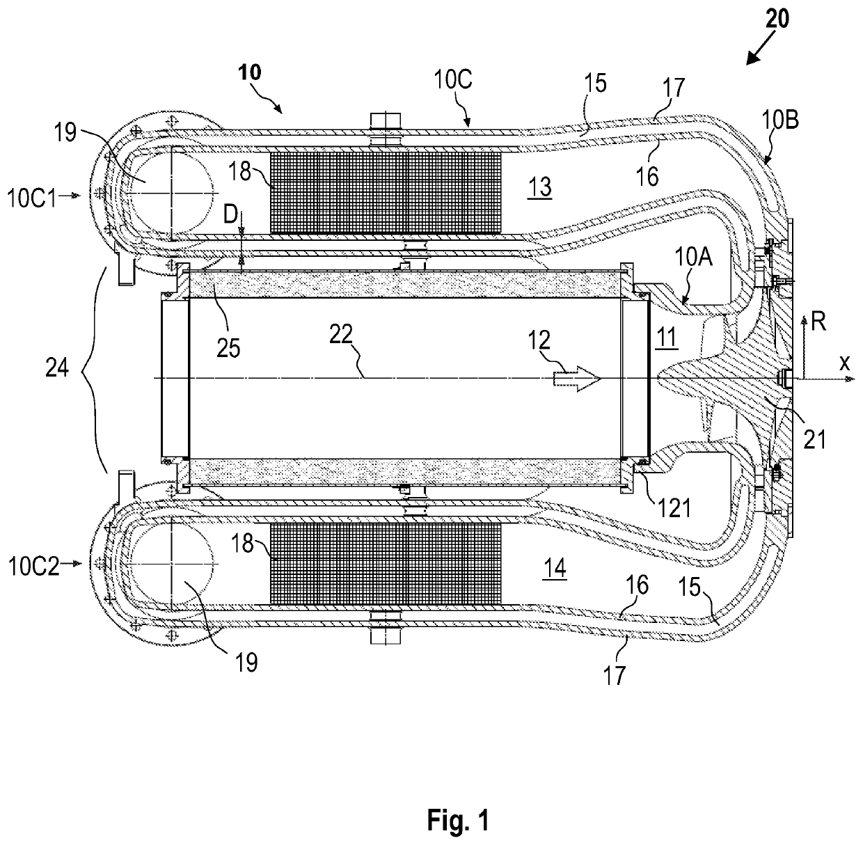
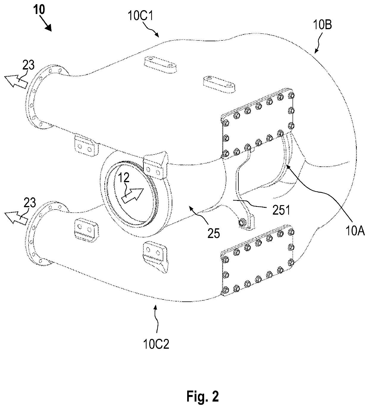
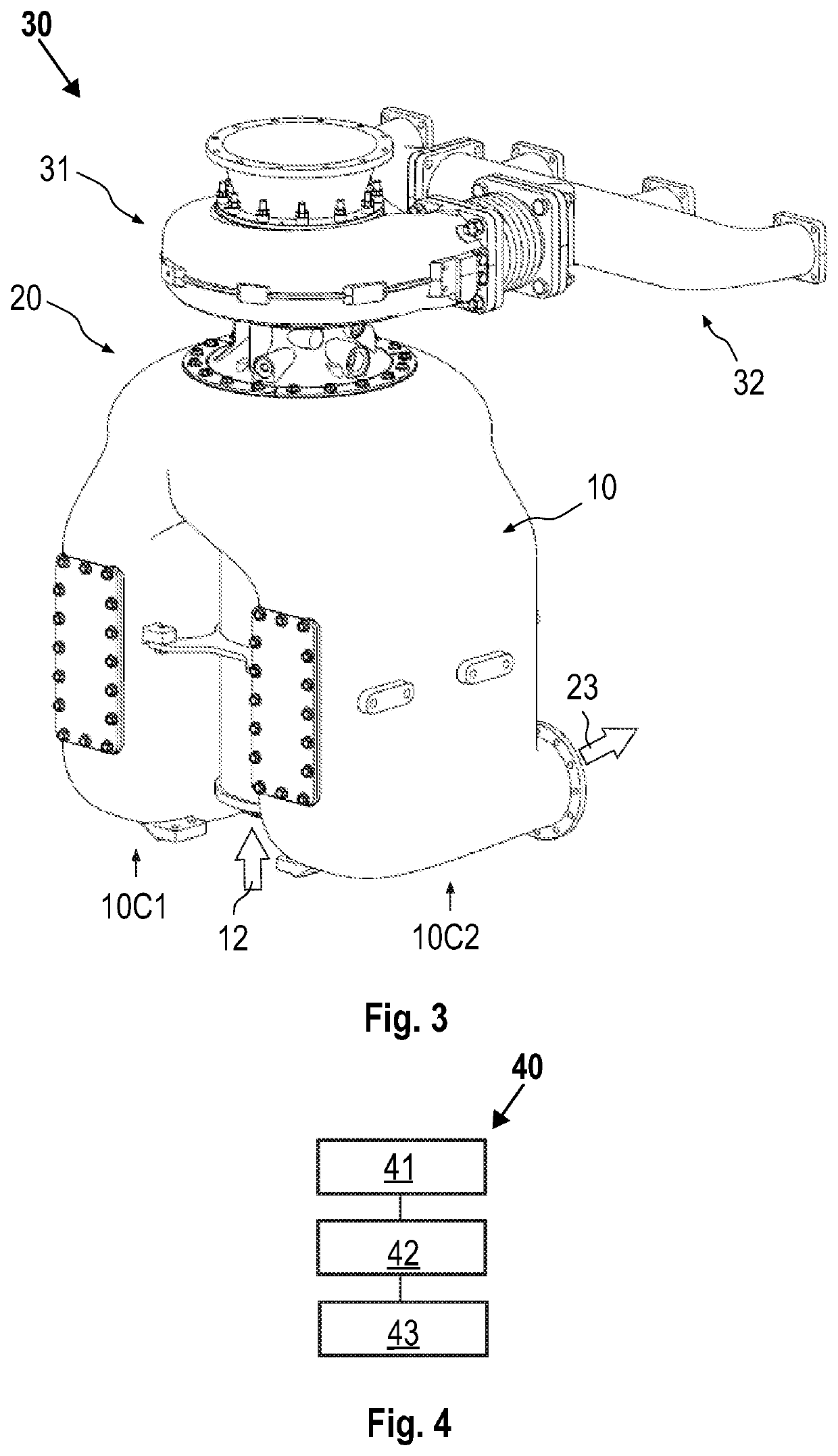
[0021]With reference to FIG. 1, a compressor housing 10 of a radial compressor according to the present disclosure is described. According to one embodiment, which can be combined with other embodiments described herein, the compressor housing 10 includes a radially inner housing region 10A, which forms an axial inflow channel 11 in an intake region of the radial compressor 20. Furthermore, the compressor housing 10 includes a diffuser region 10B adjoining the radially inner housing region 10A. The diffuser region 10B is designed to deflect a radial flow downstream of a compressor impeller 21 in an axial direction counter to the inflow direction 12 of the inflow channel 11. Furthermore, the compressor housing 10 includes a radially outer housing region 10C, which adjoins the diffuser region 10B, extends axially counter to the inflow direction 12 and provides one or more charge air collection chambers 13, 14.

[0022]Thus a compressor housing of a radial compressor which is improved ove...


PUM


Abstract

The disclosure relates to a compressor housing of a radial compressor. The compressor housing includes a radially inner housing region which forms an axial inflow channel in an intake region of the radial compressor. The compressor housing also includes a diffusor region which adjoins the radially inner housing region. The diffusor region is designed to deflect a radial flow downstream of a compressor impeller into an axial direction counter to an inflow direction of the inflow channel. The compressor housing also includes a radially outer housing region which adjoins the diffusor region, extends axially counter to the inflow direction and provides one or more charge air manifolds.

Description

CROSS REFERENCE TO RELATED APPLICATIONS[0001]This patent application is a National Stage Entry of PCT / EP2020 / 054506 filed on Feb. 20, 2020, which claims the benefit and priority of European Patent Application No. 19158292.3 filed on Feb. 20, 2020, the disclosures of which are incorporated by reference herein in their entirety as part of the present application.BACKGROUND[0002]The disclosure relates to the area of exhaust turbochargers for pressure-charged internal combustion engines. In particular, the disclosure relates to a compressor housing of a radial compressor. Furthermore, the disclosure relates to a radial compressor having a compressor housing of this kind, to an exhaust turbocharger having a radial compressor of this kind, and to an internal combustion engine having an exhaust turbocharger of this kind. Moreover, the disclosure relates to a method for feeding charge air into an internal combustion engine, in particular by means of the compressor housing.[0003]To boost the...

Claims


Application Information

Patent Timeline
Patent Type & Authority Applications(United States)
IPC IPC(8): F02M31/20F04D29/42F04D29/44F04D29/66
CPCF02M31/20F04D29/664F04D29/441F04D29/4206F04D29/4253F04D29/5826F05D2220/40F05D2250/51F05D2250/52Y02T10/12F04D29/284F05D2210/12F05D2250/50
Inventor MATHEY, CHRISTOPHALBIEZ, BERND
Owner TURBO SYST SWITZERLAND LTD
Why Eureka
Try Eureka