Hydrogenated liquid fuel production and induction system for gasoline and diesel internal combustion engines

a technology of liquid fuel and hydrogen, which is applied in the direction of combustion engines, charge feed systems, non-fuel substance addition to fuel, etc., can solve the problems of not being able to consistently deliver optimal amounts of hydrogen, and unable to achieve the proper introduction of measured quantities of hydrogen, so as to reduce the consumption of fossil fuel, minimize the loss of efficiency, and improve the efficiency of fossil fuels

Active Publication Date: 2020-01-07
SALUS ENERGY SOLUTIONS LP
View PDF7 Cites 0 Cited by
  • Summary
  • Abstract
  • Description
  • Claims
  • Application Information

AI Technical Summary

Benefits of technology

[0004]The present invention addresses the above and other needs by providing a hyperbaric fuel system which produces hydrogenated liquid fuel for combustion reactions of compression or spark ignition engines and improves fossil fuel efficiency without requiring major changes to existing fuel systems. The hydrogenated liquid fuel decreases the NOx, CO and unburned hydrocarbon particulate matter, and reduces the consumption of fossil fuel. The systems produces hydrogen gas and dissolves the hydrogen gas in the liquid fuel using several chambers, including a hyperbaric chamber, between the liquid fuel supply and a fuel pump supplying the hydrogenated liquid fuel to fuel injectors. Unused hydrogen gas and hydrogenated liquid fuel is recirculated to minimize loss of efficiency. The system preferably includes a water reservoir and electrolysis device to generate the hydrogen gas.
[0005]In accordance with one aspect of the invention, there is provided a hyperbaric mixing chamber. Hydrogen is produced, compressed and delivered at predetermined pressures into the hyperbaric mixing chamber, which causes the hydrogen gas to compress and suspend in the fossil fuel. The hydrogen gas is not injected into the moving fuel stream but, rather, is dissolved / suspended and thereby attaches to the carbon molecules within the liquid fuel base in the hyperbaric chamber before being directed forward in the system. The already-existing fuel system present on a given application may be adjusted / tuned to compensate for the extra energy being brought to the combustion chamber via hydrogenated fossil fuel, which will contribute further to reduced fuel consumption and overall emissions improvements.
[0006]In accordance with another aspect of the invention, there is provided a system for introducing hydrogen gas directly into the liquid fuel base and supplying and circulating hydrogenated liquid fuel to and from the fuel injectors of an internal combustion engine. The system dissolves hydrogen gas in liquid gasoline or liquid diesel fuel under pressure, much like carbon dioxide is dissolved in liquid to make carbonated beverages. Under pressure, hydrogen gas dissolves, differentiates and attaches to carbon molecules in the liquid fuel base, forming C—H bonds at the molecular level. Hydrogen dissolved / suspended in liquid fossil fuel tends to remain dissolved until agitated in a location where there is an atmosphere or some other means of escape. The presence of dissolved hydrogen in liquid fuel in the internal combustion engine's fuel injection system is safe and improves engine efficiency.
[0007]In accordance with yet another aspect of the invention, there is provided a bi-fuel (hydrogenated fossil fuel) generation system. Producing bi-fuel in the hyperbaric chamber is much more efficient with regard to the use of hydrogen gas than attempting to introduce hydrogen by injection through the air intake or under pressure into a moving or non-static fuel stream. There are no losses due to laminar airflow or cavitations in the liquid fuel base resulting from conditions or fuel pump operations. The energy contained in hyperbaric-created bi-fuel remains when the pressure in the hyperbaric mixing chamber is relaxed because where there are no outside dynamic forces to jar the product the internal pressure remains present with its compressed hydrogen content. This may be called static supercharging with added energy.

Problems solved by technology

The properties of hydrogen are such that known air induction systems lose substantial quantities of hydrogen gas, that the proper introduction of measured quantities of hydrogen is difficult to achieve, and no system has heretofore been presented that consistently delivers optimal amounts of hydrogen to the combustion chamber, nor in a manner conducive to on-the-road application.
Air induction methods have not proven to be practical or efficient.
Thus, no hydrogen fuel injection system for internal combustion engines has yet been significant in the marketplace.

Method used


Image

  • Hydrogenated liquid fuel production and induction system for gasoline and diesel internal combustion engines
  • Hydrogenated liquid fuel production and induction system for gasoline and diesel internal combustion engines

Examples


Embodiment Construction

[0013]The following description is of the best mode presently contemplated for carrying out the invention. This description is not to be taken in a limiting sense, but is made merely for the purpose of describing one or more preferred embodiments of the invention. The scope of the invention should be determined with reference to the claims.

[0014]Where the terms “about” or “generally” are associated with an element of the invention, it is intended to describe a feature's appearance to the human eye or human perception, and not a precise measurement.

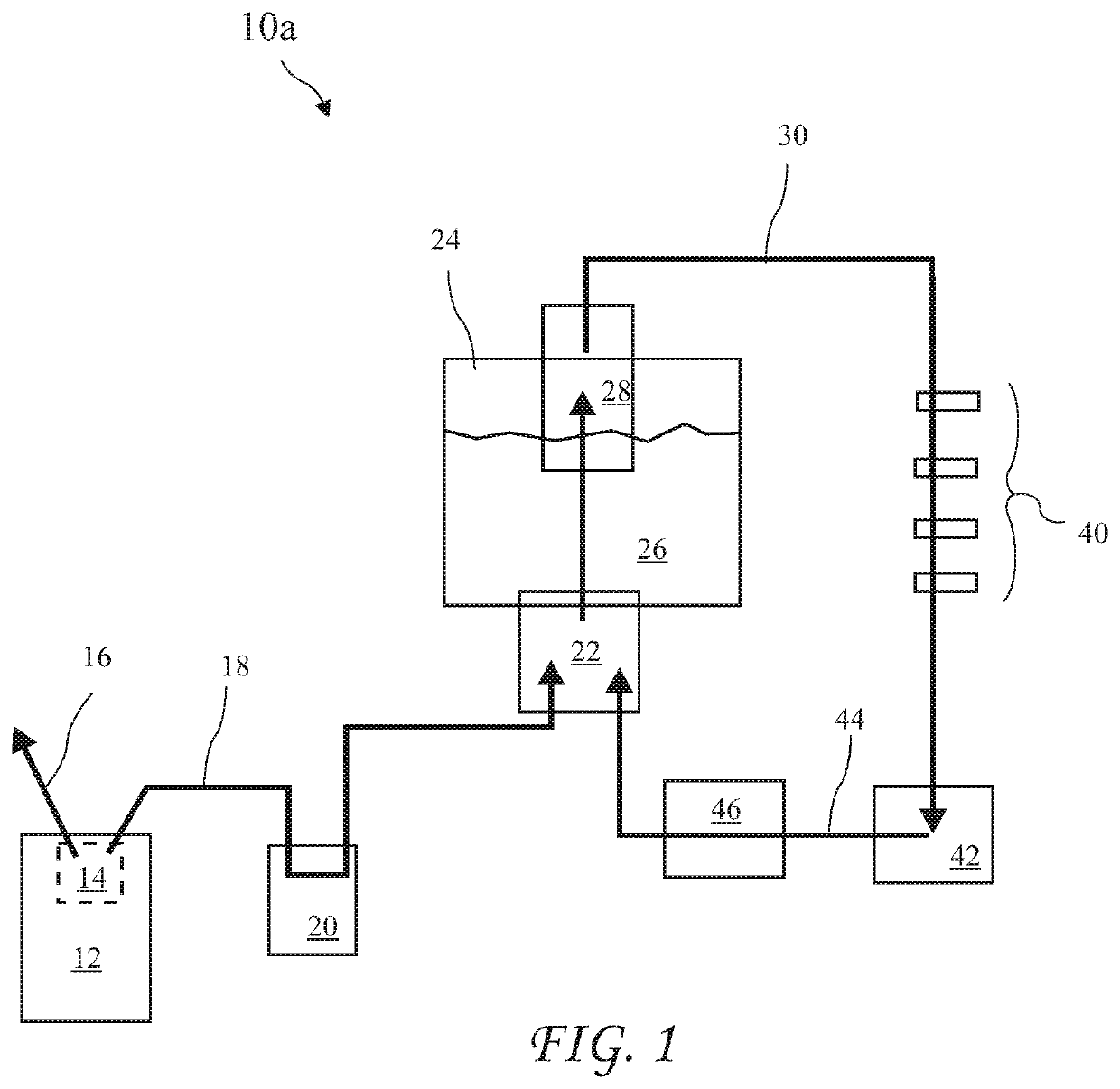
[0015]A first hydrogen induction system 10a exercising fuel pump compression is shown in FIG. 1. A hydrogen generator 12 produces hydrogen gas 18 and oxygen 16 from electrolysis of water and separates the hydrogen gas 18 from unwanted particulate and debris in a hydrogen separator 14. The hydrogen gas 18 generated by the hydrogen generator 12 passes through a cooler 20, input port 22 and fuel tank 24 (containing liquid fuel 26) and into hi...


PUM


Abstract

A hyperbaric fuel system (10a, 10b) produces hydrogenated liquid fuel (30) for combustion reactions of compression or spark ignition engines and improves fossil fuel efficiency without requiring major changes to existing fuel systems. The hydrogenated liquid fuel (30) decreases the NOx, CO and unburned hydrocarbon particulate matter, and reduces the consumption of liquid fuel (26). The systems produces hydrogen gas (18) and dissolves the hydrogen gas (18) in the liquid fuel (26) using several chambers, including a hyperbaric mixing chamber (58), between the liquid fuel supply and a fuel pump (28) supplying the hydrogenated liquid fuel (30) to fuel injectors (40). Unused hydrogen gas (18) and hydrogenated liquid fuel (30) is recirculated to minimize loss of efficiency. The system preferably includes a water reservoir and electrolysis device to generate the hydrogen gas.

Description

CROSS-REFERENCE TO RELATED APPLICATIONS[0001]The present application claims the priority of U.S. Provisional Patent Application Ser. No. 62 / 341,228 filed May 25, 2017, and PCT Application Serial No. PCT / US17 / 34560, which applications are incorporated in their entirety herein by reference.TECHNICAL FIELD[0002]The present invention relates to internal combustion engine fuel and in particular to a hyperbaric fuel system that improves fossil fuel efficiency without requiring major changes to existing fuel systems.BACKGROUND ART[0003]Known systems have attempted to deliver hydrogen gas to a combustion chamber through the air intake or by some other method of air induction. The properties of hydrogen are such that known air induction systems lose substantial quantities of hydrogen gas, that the proper introduction of measured quantities of hydrogen is difficult to achieve, and no system has heretofore been presented that consistently delivers optimal amounts of hydrogen to the combustion ...

Claims


Application Information

Patent Timeline
Patent Type & Authority Patents(United States)
IPC IPC(8): F02M37/00F02M25/12F02M25/10
CPCF02M25/12F02M37/0064F02M25/10Y02T10/121F02D19/0644F02D19/0663F02D19/0673F02D19/081F02M37/0082F02M37/14F02M37/18F02M37/0052Y02T10/30Y02T10/12
Inventor ST. MARY, HARVEY K.CHADICK, JAMES A.CORNELL, ROSS
Owner SALUS ENERGY SOLUTIONS LP
Why Eureka
Try Eureka