Determining the direction of travel of an automotive vehicle from yaw rate and relative steering wheel angle

a technology of steering wheel angle and direction of travel, applied in the direction of steering initiation, instrumentation, vessel construction, etc., can solve the problems of incorrect or unavailable gear selection information, significant more expensive than one, and sensor does not detect the turning

Inactive Publication Date: 2000-10-31
FORD GLOBAL TECH LLC
View PDF11 Cites 70 Cited by
  • Summary
  • Abstract
  • Description
  • Claims
  • Application Information

AI Technical Summary

Problems solved by technology

Examples of those situations include vehicles spins, neutral gear selection, a vehicle rolling down a grade, a vehicle lacking sufficient traction to climb a grade and sliding down in a direction opposite the selected gear, and a failure that causes the gear selection information to be incorrect or unavailable.
A sensor which measures absolute steering wheel angle provides a signal of the absolute position of the steering wheel angle relative to a known reference point and at present is significantly more expensive than one which measures relative steering wheel angle.
For example, when a relative steering wheel angle sensor is off and the steering wheel is turned, the sensor does not detect the turning.

Method used


Image

  • Determining the direction of travel of an automotive vehicle from yaw rate and relative steering wheel angle
  • Determining the direction of travel of an automotive vehicle from yaw rate and relative steering wheel angle

Examples


Embodiment Construction

)

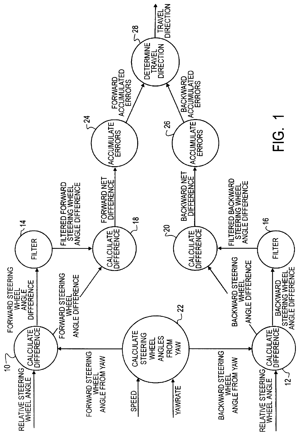
In an automotive vehicle, the inventive method is practiced using inputs from a relative steering wheel angle sensor, a yaw rate sensor, and a vehicle speed sensor. Such sensors are present in known automotive vehicles. Information from these sensors is processed electronically in an on-board processor in accordance with the inventive method. A description of the method is presented with reference to FIG. 1.

A Relative Steering Wheel Angle input from the relative steering wheel angle sensor and a Forward Steering Wheel Angle From Yaw input are processed by a difference calculation step 10 to yield a Forward Steering Wheel Angle Difference. The Relative Steering Wheel Angle input from the relative steering wheel angle sensor and a Backward Steering Wheel Angle From Yaw input are processed by a difference calculation step 12 to yield a Backward Steering Wheel Angle Difference. Each result is determined from a known relationship that applies to the respective direction of travel, and e...


PUM


Abstract

A method of using relative steering wheel angle of an automotive vehicle, vehicle yaw rate, and vehicle speed to determine whether the vehicle is traveling forward or backward. Forward and backward steering wheel angles are calculated from vehicle speed and yaw rate (22). A difference between relative steering wheel angle and forward steering wheel angle (10), and a difference between relative steering wheel angle and backward steering wheel angle (12) are calculated. The difference between relative steering wheel angle and forward steering wheel angle is filtered (14), and a difference between the filtered and the unfiltered difference between relative steering wheel angle and forward steering wheel angle is calculated to obtain a forward net difference (18). The difference between relative steering wheel angle and backward steering wheel angle is filtered (16), and a difference between the filtered and the unfiltered difference between relative steering wheel angle and backward steering wheel angle is calculated to obtain a backward net difference (20). While repeatedly performing the foregoing steps, forward net difference values derived from the forward net differences are accumulated (24), and backward net difference values derived from the backward net differences are accumulated (26). The travel direction is determined by comparing the accumulation of forward net difference values and the accumulation of backward net difference values (28). Absolute steering wheel angle and road bank angle can also be calculated.

Description

1. Field of the InventionThis invention relates generally to automotive vehicle dynamics, and more particularly to improvements in processing data from certain on-board sensors, including a steering wheel relative position sensor and a yaw rate sensor, to derive information useful for control of certain aspects of vehicle dynamics through one or more control systems.2. Background InformationCertain motion sensors, such as steering wheel position sensors and yaw rate sensors for example, provide useful inputs to an automotive vehicle control system. Such a control system utilizes a microprocessor that processes data, including input signal measurements received from such sensors, to cause adjustments in and / or actuations of control devices. The responses of such sensors can be sufficiently fast in relation to vehicle motion that their signal measurements can very closely track changing values of the respective measured parameters in real time. Accordingly, a microprocessor-based cont...

Claims


Application Information

Patent Timeline
Patent Type & Authority Patents(United States)
IPC IPC(8): B60T8/172B60T8/17B60W30/18
CPCB60T8/172B60T2210/22B60W2520/14B60W30/18036B60T2230/08B60W2540/18
Inventor JOYCE, JOHN PATRICK
Owner FORD GLOBAL TECH LLC
Why Eureka
Try Eureka