Wing profile sail

a profile sail and sail technology, applied in the direction of propulsive elements, floating buildings, vessel construction, etc., can solve the problems of not being entirely easy to handle, not being as large or efficient as desired, and not being able to achieve the effect of optimal profiling

Inactive Publication Date: 2000-11-07
LYNGHOLM TORE
View PDF11 Cites 12 Cited by
  • Summary
  • Abstract
  • Description
  • Claims
  • Application Information

AI Technical Summary

Benefits of technology

to provide a wing profile sail which can s

Problems solved by technology

In the hitherto known wing profile sails no success has been achieved in obtaining an entirely favourable profiling, with the result that the above-mentioned driving force on the sail and thereby on the boat has not b

Method used


Image

  • Wing profile sail
  • Wing profile sail
  • Wing profile sail

Examples


Embodiment Construction

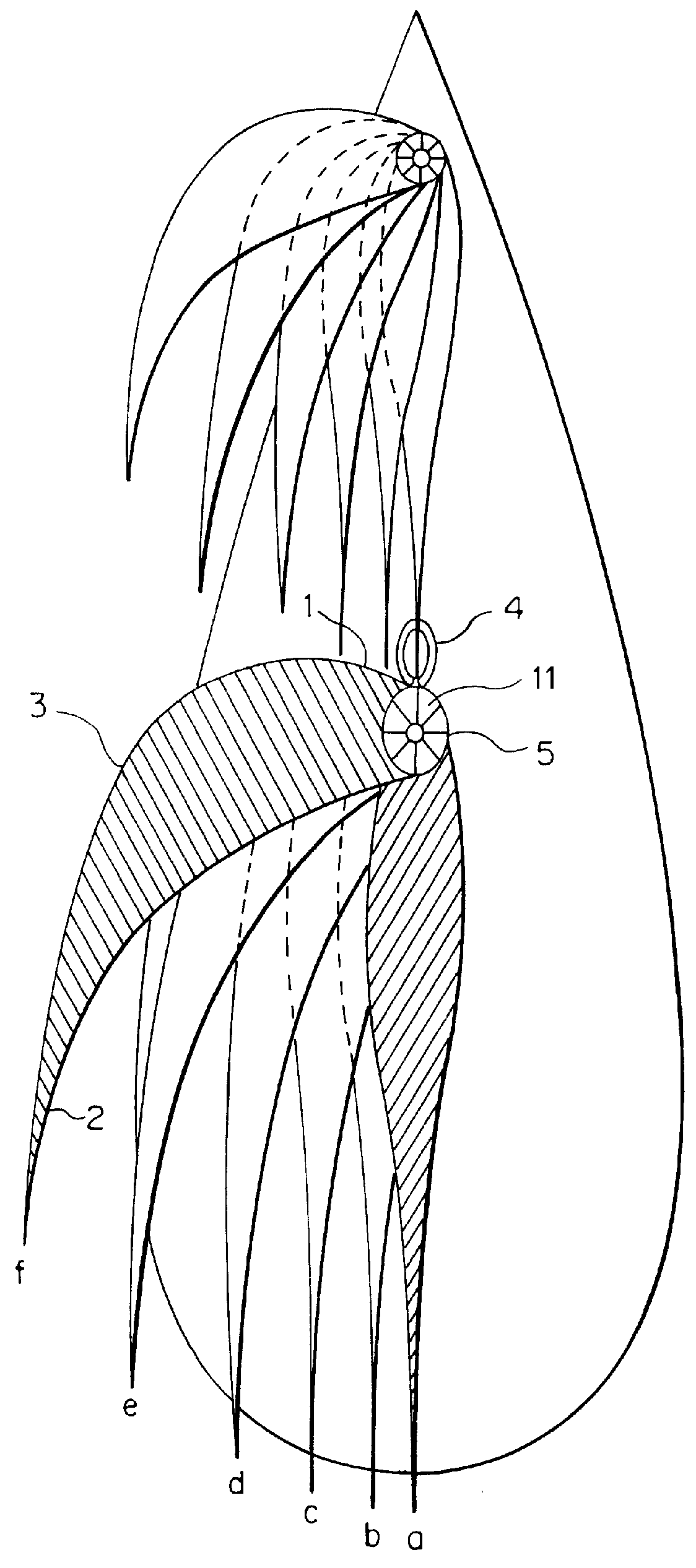
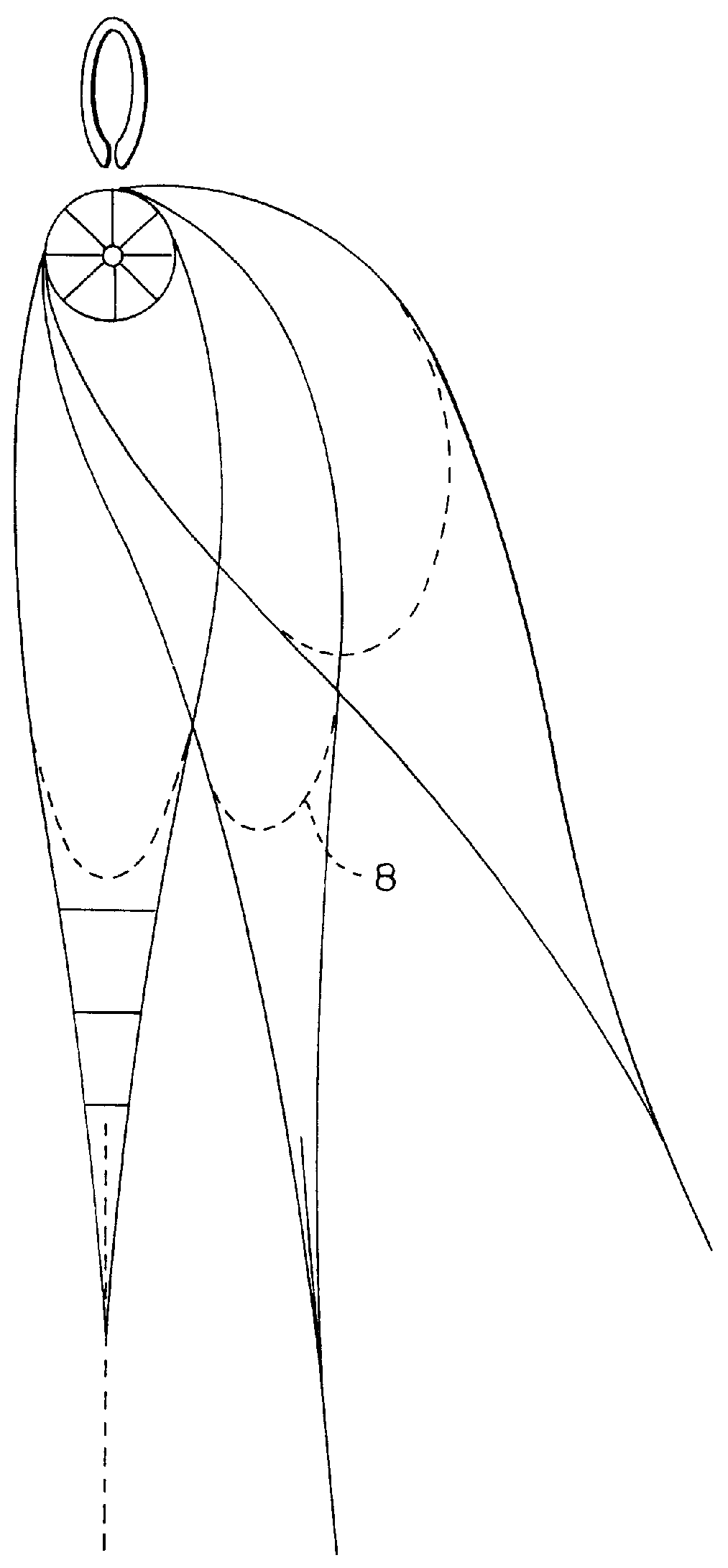
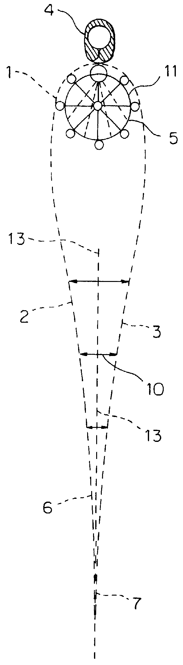
FIG. 1 of the drawing is a purely schematic illustration of how the aerodynamic shape of a wing profile sail according to the invention changes with different angles of incidence of the wind. The drawing illustrates a boat with a mast 4 on which there is mounted a sail and where in the boat's forward section there is mounted a corresponding foresail or jib on a not illustrated forestay. The sail profile's thickness and shape will be altered in relation to the sail's sheet angle.

As shown in the figure the sail has a rounded front edge 1, which is attached in a suitable fashion to the mast 4 or the forestay. The sail is attached to the stay or the mast and tightened up in its longitudinal direction. The rounded shape of the sail's front edge 1 has been achieved by placing in the forward area of the sail's inner space a conical, inflatable body, which is stretched and kept taut by the tightening of the sail. The sail has two separate cloths, which are designated by 2 on the windward si...


PUM


Abstract

PCT No. PCT/NO97/00337 Sec. 371 Date Aug. 11, 1999 Sec. 102(e) Date Aug. 11, 1999 PCT Filed Dec. 15, 1997 PCT Pub. No. WO98/26982 PCT Pub. Date Jun. 25, 1998A wing profile sail is in the form of a sailcloth which defines an airfoil-shaped space, which is filled with air through openings or one-way closing mechanisms. At the sail's luff (1) there is provided a bag/lung-shaped body which can be filled with air and which is extendable in the height direction and which in an extended state forms an upwardly tapering conical, cylindrical body (11). The sail's outer cloth (2, 3) extends from this body (11) and is transferred on each side from this body (11) and is attached at a distance from the after leech (7), the sail's after part (7) being composed of one sailcloth surface. From the outer sailcloth's (2, 3) attachment area, in the inner spaces of the sail there is provided an intermediate sailcloth, which at least covers the area of the openings for air supply. The outer sailcloths (2, 3) are connected in the sail's bottom area in order to form the inner spaces in such a manner that the outer sailcloths are movable in relation to each other.

Description

Technical Field of the InventionThe invention concerns a wing profile sail wherein a sailcloth defines an airfoil-shaped space which can be filled with air through openings equipped within one-way closing mechanisms.Over the years a number of different types of wing profile sails have been developed in the field of sails for sailing boats, where attempts have been made to give the sail surfaces the most aerodynamically favourable shape in order to achieve maximum utilisation of the wind forces. A variety of models have been developed from profiled masts in which the actual sail forms an extension of the mast profile, to sails where the sailcloth defines spaces, which may have the aerodynamic shape of airfoils. Examples of these can be found, e.g., in British patent publication 2196310 and U.S. Pat. Ser. No. 4,753,186. In the British publication stays are used for forming the sail's outer surfaces in the most favourable way possible and for changing the sail's profile according to wi...

Claims


Application Information

Patent Timeline
IPC IPC(8): B63H9/06B63H9/10B63H9/00B63H9/061
CPCB63H9/1035B63H9/0614B63H9/0615
Inventor LYNGHOLM, TORE
Owner LYNGHOLM TORE
Why Eureka
Try Eureka