Lap splicing apparatus with the trailing tail end of the splice always on the same side

a splicing apparatus and tail end technology, applied in the field oflap splicing apparatus, can solve the problems of more complicated machinery and additional space, and achieve the effect of convenient and economical use and manufactur

Inactive Publication Date: 2000-11-07
CTC INT
View PDF11 Cites 9 Cited by
  • Summary
  • Abstract
  • Description
  • Claims
  • Application Information

AI Technical Summary

Benefits of technology

It is a still further object of the present invention to provide a lap

Problems solved by technology

Many end users do not like this arrangement since it may cause problems with the machinery downstream of the splicing assembly.
In such case, the new roll is always indexed to the same position durin

Method used


Image

  • Lap splicing apparatus with the trailing tail end of the splice always on the same side
  • Lap splicing apparatus with the trailing tail end of the splice always on the same side
  • Lap splicing apparatus with the trailing tail end of the splice always on the same side

Examples


Embodiment Construction

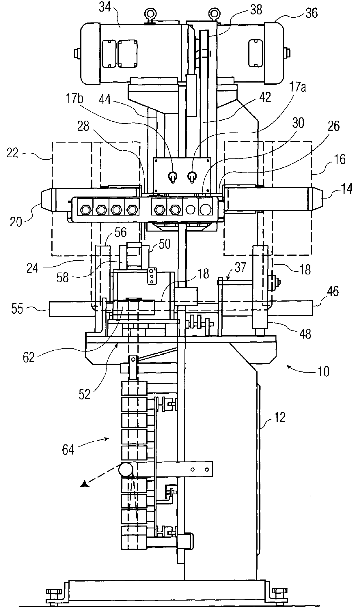
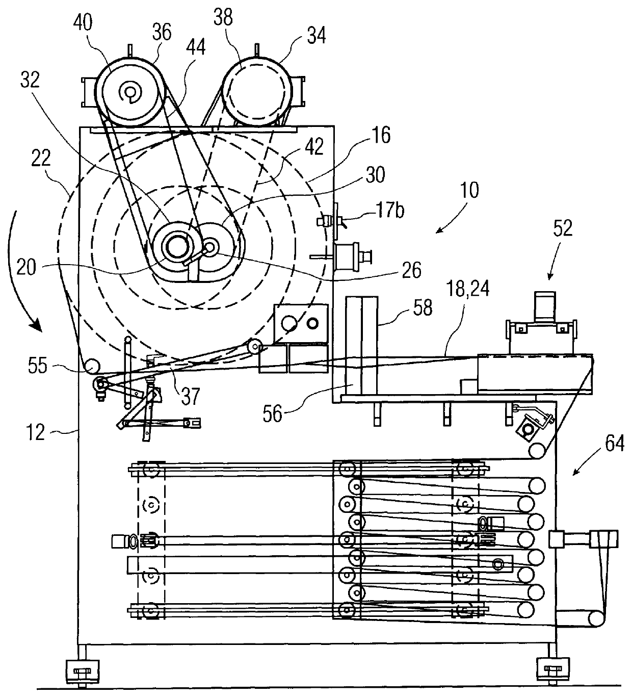
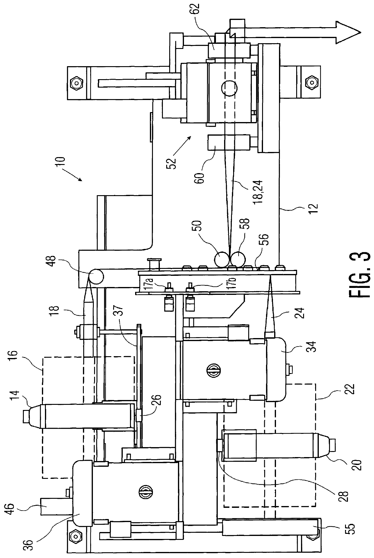
Referring to the drawings in detail, and initially to FIGS. 1-3, a lap splicing apparatus 10 according to the present invention includes a frame 12 having a first spindle 14 rotatably mounted at a first fixed position and containing a roll 16 with a first web 18 thereon. A second spindle 20 is rotatably mounted at a second fixed position on the opposite side of frame 12 for holding a roll 22 containing a second web 24 of material thereon. The web material with which the present invention is intended to be used is preferably a narrow width web material, as shown best in FIGS. 1 and 3, for example, in the range of approximately one to three inches, although the present invention is not limited thereby. Thus, the web material is preferably a narrow ribbon which can be easily turned in direction as will be understood from the description hereinafter.

First and second spindles 14 and 20 are rotatably mounted about parallel axes. Each spindle can include an air chuck or other arrangement f...


PUM

PropertyMeasurementUnit
Angleaaaaaaaaaa
Timeaaaaaaaaaa
Pressureaaaaaaaaaa

Abstract

A lap splicing apparatus for lap splicing first and second webs together, with each of the first and second webs alternately constituting a running web and a new web to be spliced to the running web, includes a frame; a first spindle mounted at a first fixed position on the frame for holding a roll containing the first web at a first orientation; a second spindle mounted at a second fixed position on the frame for holding a roll containing the second web at the first orientation; a single lap splicing device immovably mounted at a fixed position on the frame for lap splicing the first and second webs together with the trailing tail end of the lap splice always being on the same side; a first transfer assembly of rollers for bringing the first web to the lap splicing device, and for turning the first web by at least one angle from the first orientation; and second transfer assembly of rollers for bringing the second web to the lap splicing device, and for turning the second web by at least one angle from the first orientation, such that the running web is at a first level and the new web is at a different, second level prior to the lap splicing operation, with the new web moving from the second level to the first level after the lap splicing operation.

Description

The present invention relates generally to apparatus for splicing webs of material together, and more particularly, is directed to a lap splicing apparatus in which the trailing tail end of the splice is always on the same side without using any turret assembly for holding the rolls of web material.In web transport machines, when a running web nears depletion, it is necessary to splice the trailing end of the running web to the leading end of a new web. There are different types of web splices. Specifically, there is a butt splice in which the ends of the webs are accurately butted together in end to end relationship. The other type of splice is a lap splice in which the leading end of the new web has a piece of double-sided tape and the opposite side of the tape is adhered to the running web at a position offset from the trailing edge thereof. As a result, there is a tail at the trailing end of the running web which overlaps the leading end of the new web.However, if the two rolls,...

Claims


Application Information

Patent Timeline
IPC IPC(8): B65H19/18
CPCB65H19/1852B65H19/1873B65H2301/46312B65H2301/4621B65H2301/46172
Inventor RYAN, RALPH L.
Owner CTC INT
Why Eureka
Try Eureka