

Stator arrangement of alternator for vehicle
a technology of stator and alternator, which is applied in the direction of magnetic circuit rotating parts, magnetic circuit shape/form/construction, windings, etc., can solve the problems of reducing the number of turns and not providing the output voltage of the alternator, increasing the difficulty of stator manufacturing steps, and increasing the production cos
- Summary
- Abstract
- Description
- Claims
- Application Information
AI Technical Summary
Problems solved by technology
Method used
Image

Examples
first embodiment
A stator core according to the present invention is described with reference to FIGS. 1-7.
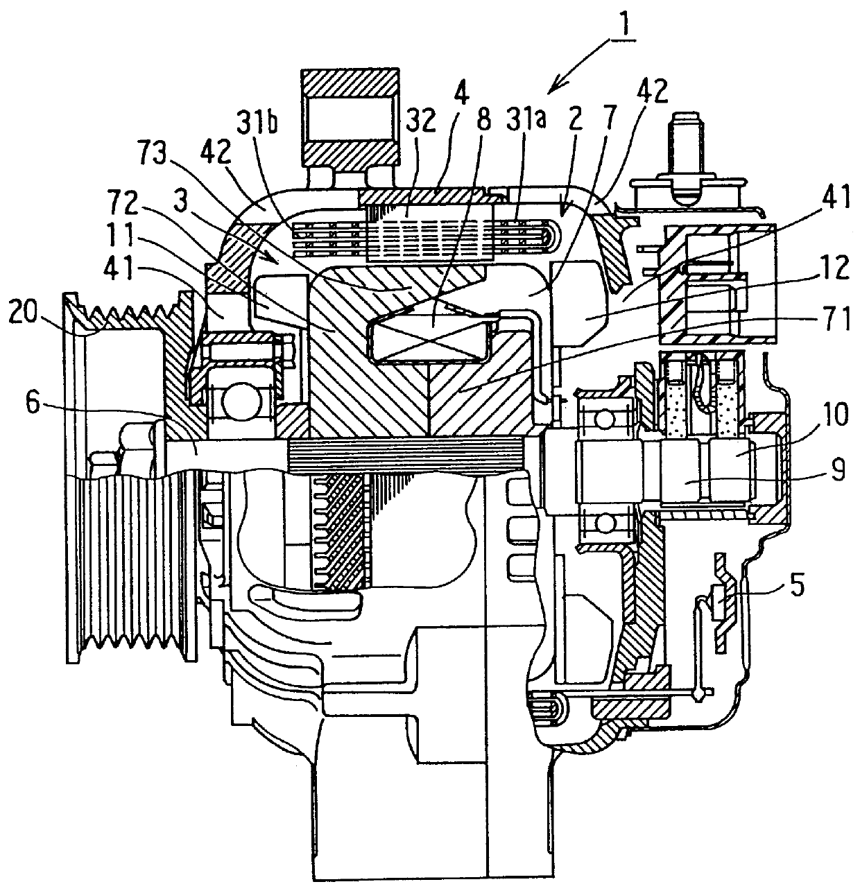
Alternator 1 is composed of stator 2 functions as an armature, rotor 3 functions as a magnetic field, housing 4 for supporting stator 2 and rotor 3, and rectifier for converting ac power to dc power. Rotor 3 rotates together with shaft 6 and is composed of Lundell type pole core 7, field coil 8, slip rings 9, 10 and cooling fans 11, 12. Shaft 6 is linked with pulley 20 to be driven by an engine (not shown) mounted on a vehicle. Lundell type pole core 7 is composed of a pair of pole core members. Each of the pole core 7 members is composed of boss portion 71 fitted to shaft 6, disk portion 72 extending radially from boss portion 71 and a plurality of claw poles 73.
Air intake windows 41 are formed on an axial end of housing 4, and air discharge windows 42 are formed on the shoulder portions of housing 4 opposite to first coil-end group 31a and second coil-end group 31b.
Stator 2 is composed of sta...
second embodiment
More conductor members in each slot than four conductor members of winding 315 of the first embodiment can be provided according to the following second to four embodiments.
A plurality of windings 316 each of which has four conductor members in each slot can be put on winding 315 of the first embodiment in the radial direction to form a series-connected winding.
First coil-end group 31a having 8 conductor members in each of slots 35 is shown in FIG. 8, and a winding diagram of X-phase winding is shown in FIGS. 9 and 10. FIG. 9 shows the conductor members disposed in four layers: outermost first layer indicated by one-dot chain lines, second layer by broken lines, third layer by solid lines and fourth layer by two-dot chain lines. FIG. 10 shows the conductor members disposed in fifth to eighth layers: fifth layer by one-dot chain lines, sixth layer indicated by broken lines, seventh layer by solid lines and eighth layer by two-dot chain lines. The windings shown in FIGS. 9 and 10 are ...
third embodiment
A plurality of winding 315 according to the first embodiment, which has four conductor members in each of slots 35, are surrounded by winding 317.
The conductor members disposed in the outer two layers, the conductor members disposed in the inner two layers and two conductor members disposed side by side are combined to form a plurality of the same windings as the first embodiment, and are connected in series. FIG. 11 is a schematic diagram showing a portion of first coil-end group 31a which has 8 conductor members in each slot. FIGS. 11 and 12 show a winding diagram of X-phase winding. FIG. 12 shows the conductor members disposed in the third to sixth layers, and FIG. 13 shows the conductor members disposed in the first, second, seventh and eighth layers.
In FIG. 12, the conductor members disposed in the third layer from the outermost layer are indicated by one-dot chain lines, the conductor members in the fourth layer are indicated by broken lines, the conductor members in the fifth...
PUM
| Property | Measurement | Unit |
|---|---|---|
| angle | aaaaa | aaaaa |
| electric angle | aaaaa | aaaaa |
| circumference | aaaaa | aaaaa |
Abstract
Description
Claims
Application Information