Tool coupling and method for coupling two tool parts

a tool and tool body technology, applied in the direction of manufacturing tools, twist drills, cutting inserts, etc., can solve the problems of poor precision in machining, screw holding the cutting insert loses its clamping force, must be retightened, etc., and achieves good precision and simple assembly

Inactive Publication Date: 2000-11-14
SECO TOOLS AB
View PDF11 Cites 170 Cited by
  • Summary
  • Abstract
  • Description
  • Claims
  • Application Information

AI Technical Summary

Benefits of technology

Still another object of the present invention is to provide a tool with good precision.
Still another o

Problems solved by technology

The strain on each individual groove becomes large and the resulting wear leads subsequently to poor precision in the machining result.
Said stamping will however happen successively and therefore the screw which h

Method used


Image

  • Tool coupling and method for coupling two tool parts
  • Tool coupling and method for coupling two tool parts
  • Tool coupling and method for coupling two tool parts

Examples


Embodiment Construction

A) Technical analysis of transferred torques in couplings

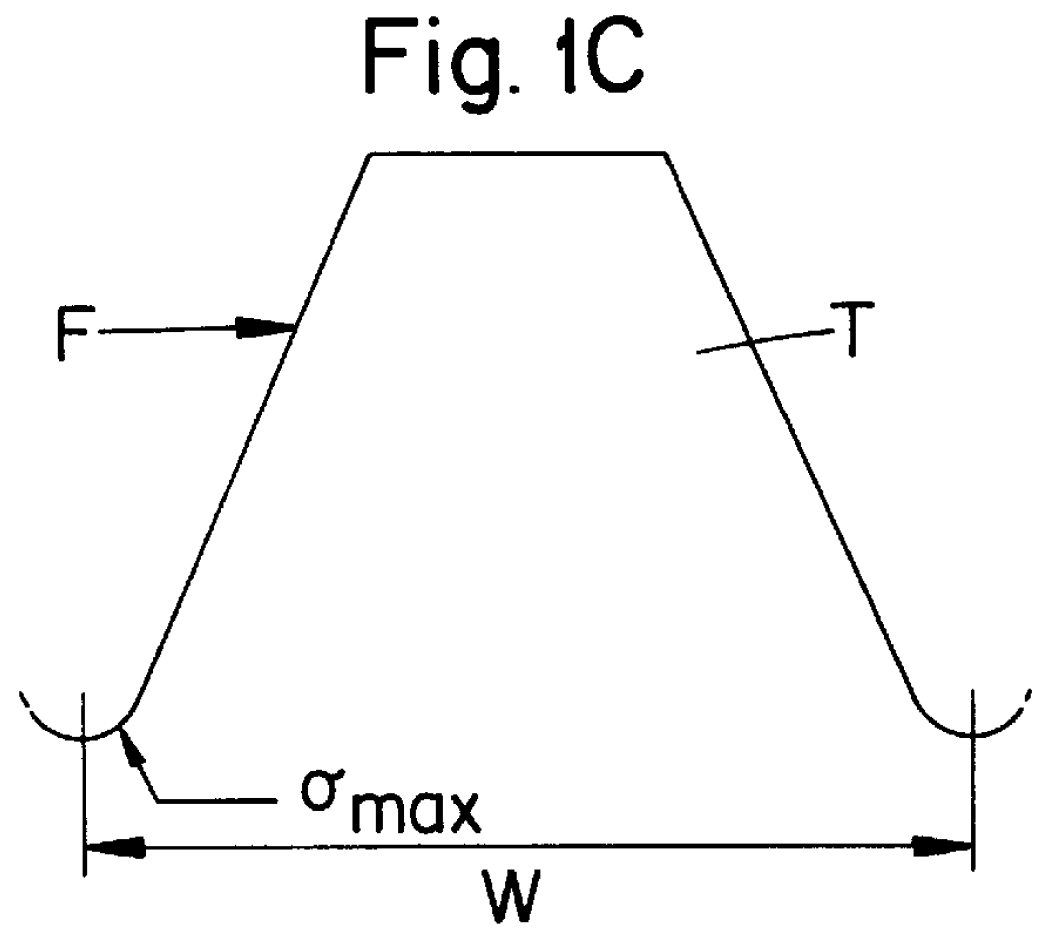
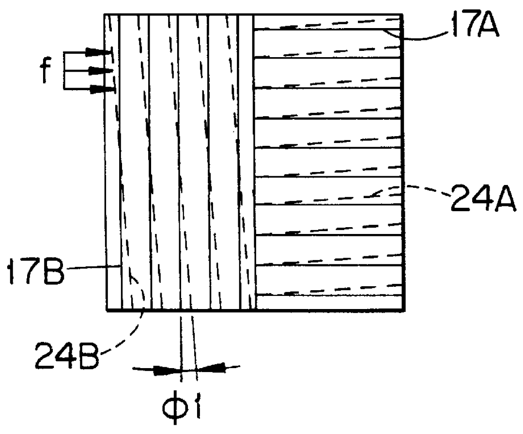
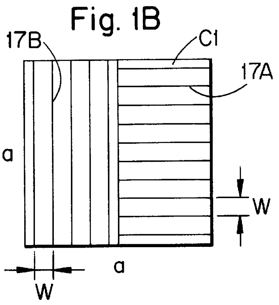
Hereinafter follows a technical analysis of a theory behind the present invention. Look at a prior art tool part having a square surface C with sides having a length a and which has N number of milled, longitudinally parallel grooves G, each groove having a width or partition W, see FIG. 1A. Teeth are formed between adjacent grooves. If that surface were pressed against another part having an opposite surface with similar grooves it is assumed that for an individual groove a relative torsion (turning) can be made between the parts within a certain angle .phi.1. This can be said to be the measure of the gap (clearance) between the ridges of one part and the grooves of the other part due to normal manufacturing tolerances. When N grooves simultaneously influence each other a cooperation is obtained which reduces the total relative torsion inverted proportionally with the number of grooves whereby the total relative torsion is de...


PUM

PropertyMeasurementUnit
Angleaaaaaaaaaa

Abstract

A tool includes a cutting head and a holder, wherein the cutting head and the holder form two cooperating surfaces that are pressed together. The surfaces possess rows of alternating parallel grooves and ridges for locking the surfaces to each other. Each of the surfaces has two rows of grooves, one row oriented 90 DEG relative to the other row. On one of the surfaces, some of the grooves of one row are in non-intersecting relationship with the grooves of the other row. On the other surface, the rows extend completely across one another, whereby the rows together form a waffle-like pattern. The cooperating surfaces allow at least four separate relative positions between the cutting head and holder.

Description

The present invention relates to a coupling, a tool, a cutting head, a holder, a shim and a method of coupling two tool parts together. In particular, the invention pertains to locking two tool parts together by a ridge-groove structure formed in opposing surfaces of the parts.From German Document No. 34 46 455 there is previously known a turning tool having a coupling comprising two grooved surfaces forced together, whereby teeth of each surface enter grooves of the other surface to lock the surfaces together. The known tool has four teeth at the lower side of cutting insert which cooperate with corresponding grooves in the holder. The strain on each individual groove becomes large and the resulting wear leads subsequently to poor precision in the machining result. The same applies for a tool according to German Document C2-34 48 086 and German Document No. OS-19 50 718 which include radially projecting teeth.Disclosed in U.S. Pat. No. 5,682,803 is another turning tool of the above...

Claims


Application Information

Patent Timeline
IPC IPC(8): B23B27/16B23B27/00B23B27/08B23B31/00B23C5/10B23B51/02
CPCB23B27/08B23B31/008B23B51/02B23C5/10B23C5/1054B23B27/1622Y10T407/2272B23B2200/165B23B2200/167B23B2205/02B23B2205/16B23B2251/02B23B2260/132B23C2210/03Y10T407/2274Y10T407/192Y10T407/227B23B29/06
Inventor RYDBERG, CHRISTERKOSKINEN, JORMA
Owner SECO TOOLS AB
Why Eureka
Try Eureka