Tool and clamp for chip removing machining

a technology for chip removal and clamping, which is applied in the direction of turning tools, turning apparatuses, maintainance and safety accessories, etc., can solve the problems of plastic deformation of the clamp, and the inability to hold solid (non-recessed, non-apertured) cutting inserts with planar surfaces

Inactive Publication Date: 2000-11-14
SECO TOOLS AB
View PDF13 Cites 26 Cited by
  • Summary
  • Abstract
  • Description
  • Claims
  • Application Information

AI Technical Summary

Benefits of technology

Still another object of the present invention is to provide a tool in which a planar cutting insert can be rigidly clamped.

Problems solved by technology

A drawback of the known tool is that the cutting insert must include said recess such that the clamp can function satisfactorily.
Another drawback is that plastic deformation of the clamp can occur.
Furthermore, solid (non-recessed, non-apertured) cutting inserts with planar surfaces cannot be satisfactorily held by means of the known device.

Method used


Image

  • Tool and clamp for chip removing machining
  • Tool and clamp for chip removing machining
  • Tool and clamp for chip removing machining

Examples


Embodiment Construction

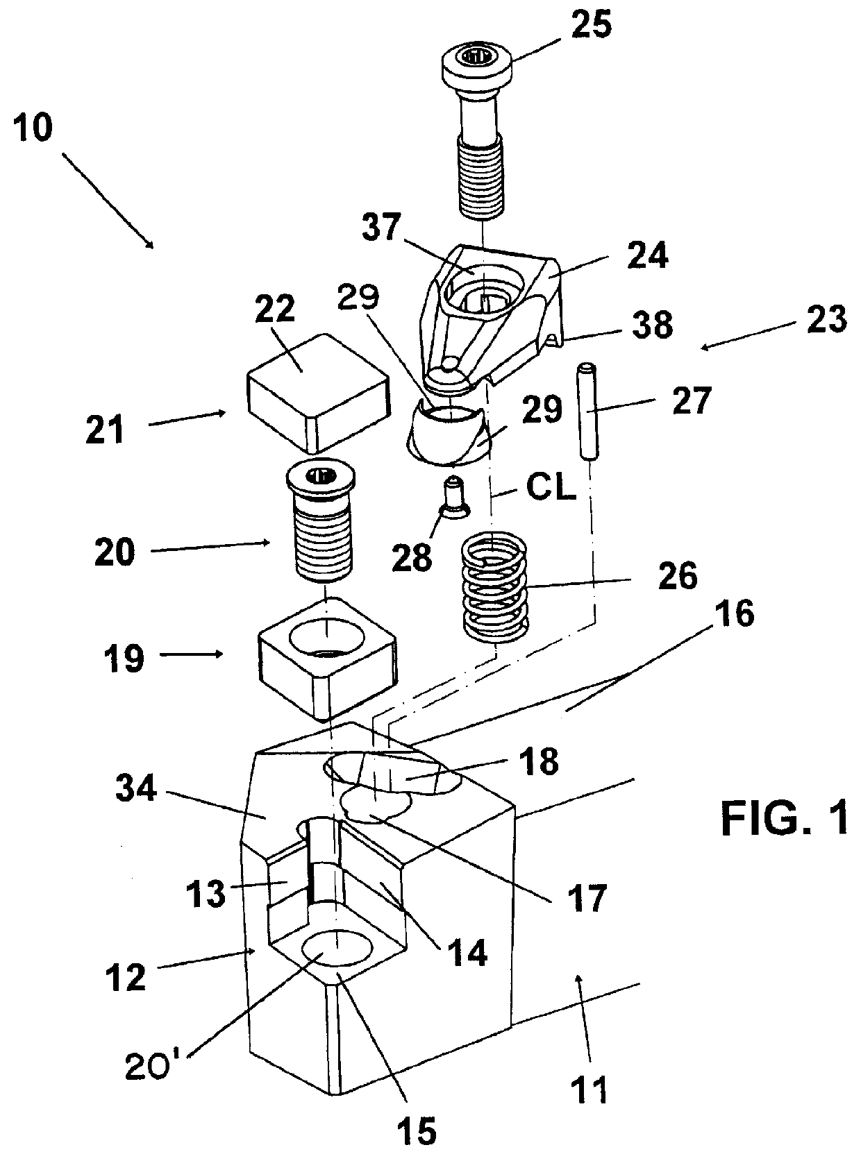
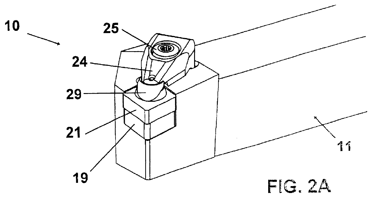
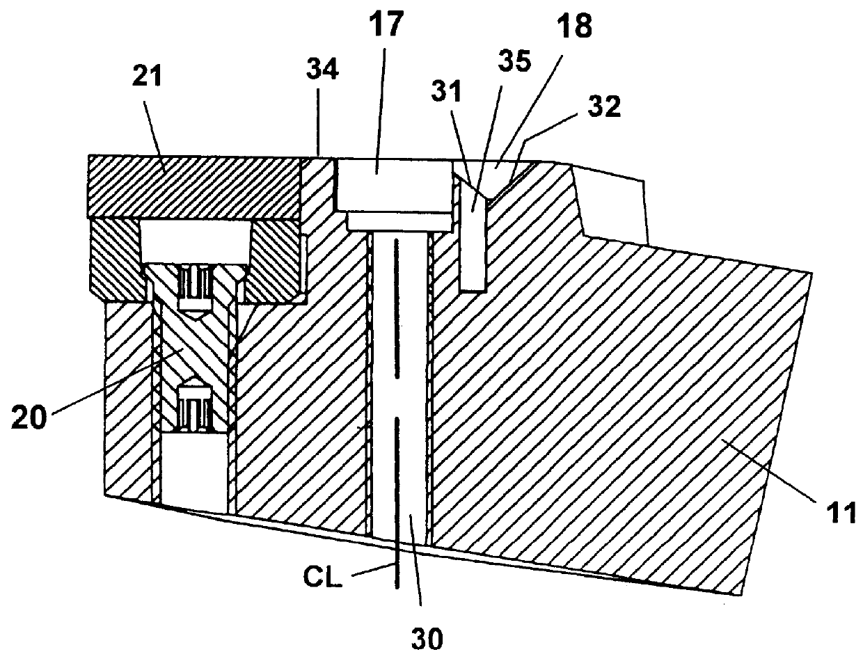
The tool 10, FIG. 1, comprises a cutting insert holder 11 intended for turning, which in its forward end ends in a taper, wherein there is provided a cutting insert pocket 12 with two support surfaces 13, 14 angled relative to each other, as well as a bottom surface 15. The bottom surface contains a threaded hole 20'. The holder has a shank 16. A first recess 17 is provided between the cutting insert pocket 12 and the shank. The recess 17 connects to a second recess or slot 18 provided closer to the shank in direction F (see FIG. 2B). The tool 10 further comprises a shim 19 provided to be forced against the bottom surface by a fastening screw 20 that is threadably received in the hole 20'. Furthermore, a cutting insert 21 is intended to abut against the shim 19 and against the support surfaces 13, 14. The cutting insert 21 has a polygonal basic shape with substantially planar and parallel side faces 22. In some cases only the central portions of the cutting insert may be planar and ...


PUM

PropertyMeasurementUnit
angleaaaaaaaaaa
angleaaaaaaaaaa
displacementaaaaaaaaaa

Abstract

A tool for chip removing metal machining includes a holder, a solid cutting insert mounted in a pocket of the holder, and a clamp for securing the insert. The clamp includes a clamping surface frictionally engaging a planar upper surface portion of the insert. The clamp is attached to the holder by a screw causing a downward projection of the clamp to slide along a sloping surface of the holder in order to displace the clamp and the insert rearwardly until the insert abuts an upstanding support surface of the holder. As the clamp is being tightened-down by the screw, an elastic lip of the clamp is elastically deformed by a surface of the holder to tilt the clamp in a direction causing the clamping surface to bear more firmly against the insert. A stop arrangement terminates the tightening down of the clamp before the clamp is plastically deformed.

Description

The present invention relates to a tool for chip removing machining, and especially to an apparatus and method for clamping a cutting insert in place.PRIOR ARTThrough U.S. Pat. No. 4,480,950 or U.S. Pat. No. 5,100,268, a tool of above type is previously known. The known tool comprises a clamp by which a cutting insert is clamped against a cutting insert pocket in a holder. The forward end of the clamp includes a projection which cooperates with a recess in the cutting insert such that the cutting insert is pushed both downwards and inwards at tightening of a screw which acts on the mid section of the clamp. The rear end of the clamp comprises an oblique surface that cooperates with an oblique surface on the holder. The clamp is moved during said tightening. A drawback of the known tool is that the cutting insert must include said recess such that the clamp can function satisfactorily. Another drawback is that plastic deformation of the clamp can occur. Furthermore, solid (non-recess...

Claims


Application Information

Patent Timeline
Patent Type & Authority Patents(United States)
IPC IPC(8): B23B27/16
CPCB23B27/1666Y10T407/2292Y10T407/2286Y10T407/2282Y10T407/229B23Q11/00
Inventor JANSSON, MIKAEL
Owner SECO TOOLS AB
Why Eureka
Try Eureka