Synchronous rectifier circuit

a rectifier element and synchronous technology, applied in the direction of electric variable regulation, process and machine control, instruments, etc., can solve the problems of forward voltage loss of the rectifier element, low efficiency of light-load operation,

Inactive Publication Date: 2000-11-21
SHARP KK
View PDF3 Cites 55 Cited by
  • Summary
  • Abstract
  • Description
  • Claims
  • Application Information

AI Technical Summary

Problems solved by technology

However, the synchronous rectifier circuit 101 having the described structure has a problem that the efficiency is often lowered in light-load operation.
Thus, a loss, such as a forward voltage loss of the rectifier element, which occurs when a current flows through the rectifier element is not generated.

Method used


Image

  • Synchronous rectifier circuit
  • Synchronous rectifier circuit
  • Synchronous rectifier circuit

Examples


first embodiment

The above First Embodiment described the switching power circuit 1 of a step-down type. However, not limiting to this, the present invention is also applicable to a switching power circuit of other types. The present embodiment will describe the case where a step-up type is adopted as an example of such a switching power circuit.

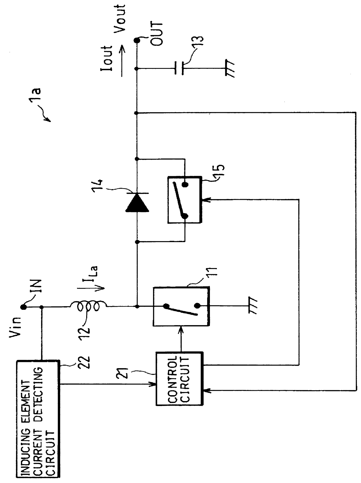
As shown in FIG. 3, in a switching power circuit 1a of a step-up type, one terminal of an inducing element 12 is connected to an input terminal IN, and the other terminal is grounded via a first switch 11. The junction of the inducing element 12 and the first switch 11 is connected to an output terminal OUT via a parallel circuit composed of a commutating diode 14 and a second switch 15. The polarity of the commutating diode 14 is set in a direction for maintaining current I.sub.La of the inducing element 12, that is, in a direction from the inducing element 12 to the output terminal OUT. Between the output terminal OUT and GND is provided a smoothing capaci...

fourth embodiment

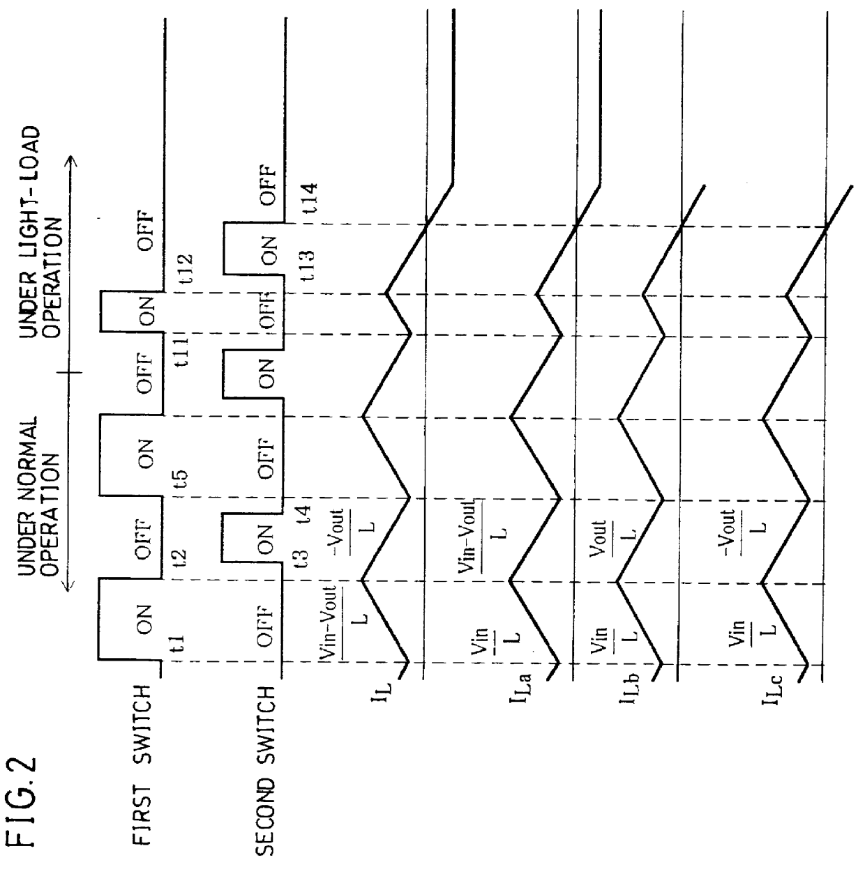
The fourth embodiment describes, referring to FIG. 2 and FIG. 5, the case where an up-down type is adopted as an application example of the switching power circuit. As shown in FIG. 5, in a switching power circuit 1c of an up-down type, though the structure is substantially the same as that of the switching power circuit 1a of FIG. 3, a capacitor 16 is provided between (i) the junction of an inducing element 12 and a first switch 11 and (ii) a commutating diode 14, and the junction of the capacitor 16 and the commutating diode 14 is grounded via a short-circuiting inducing element or a short-circuiting resistance of an impedance element ("Z" in FIG. 5) 17. The other structure is the same as that of the switching power circuit 1a, and members having the same functions are given the same reference numerals and explanations thereof are omitted here.

In this structure, as shown in FIG. 2, induction current I.sub.Lc flowing through the inducing element 12 is increased while the first swit...

fifth embodiment

The fifth Embodiment described the case where the voltage integration control circuit is provided in the switching power circuit of a step-down type. However, not limited to this, the present invention is also applicable to a switching power circuit of other types. For example, when a voltage integration control circuit 23a, instead of the inducing element current detecting circuit 22, is provided in the switching power circuit 1a of a step-up type as shown in FIG. 3, a switching power circuit 2a of FIG. 7 is obtained.

In a structure of the switching power circuit 2a, the induction current I.sub.La in the conduction period of the first switch 11 is changed in accordance with Equations (3) and (4), and the time x.sub.a it takes until the energy stored in the inducing element 12 in the conduction period of the first switch 11 is released is determined by the following Equation (10).

x.sub.a =T.sub.ON .multidot.Vin / (Vout-Vin) (10)

Thus, as with the Fifth Embodiment, when the voltage integ...


PUM


Abstract

In a switching power circuit adopting the synchronous rectifying system, when a first switch is cut-off, current IL of an inducing element is maintained by a commutating diode, and the inducing element releases an energy which was stored in a conduction period of the first switch. A second switch connected in parallel to the commutating diode is conducted so as not to be overlapped with the conduction period of the first switch. In the conduction period of the second switch, the current IL does not flow through the commutating diode, and it is possible to prevent lowering of efficiency caused by forward voltage drop. An inducing element current detecting circuit monitors the current IL and, when the current IL is reversing its direction, instructs a control circuit to cut-off the second switch. As a result, no reverse current flows through the inducing element even when the load is small, thus realizing a switching power circuit always having high efficiency.

Description

1. Field of the InventionThe present invention relates to a synchronous rectifier circuit adopting a synchronous rectifying system, which is one type of switching power circuits in which input power is outputted after interrupting the input power in proportion to a predetermined output and after smoothing, and particularly relates to a synchronous rectifier circuit whose efficiency is not lowered even in light-load operation.2. Description of the Background ArtSwitching power circuits have been widely used conventionally as small power circuits having high efficiency. The switching power circuits output an input power after interruption and smoothing, and adjust the proportion of the input power when interrupting in accordance with an output voltage or output current, thus supplying a voltage or current of a constant value to a load, regardless of a change in load.In recent years, various methods have been proposed to further improve the efficiency of the switching power circuit, an...

Claims


Application Information

Patent Timeline
Patent Type & Authority Patents(United States)
IPC IPC(8): H02M3/158H02M3/04H02M1/38H02M3/155
CPCH02M1/38H02M3/1588Y02B70/1466Y02B70/10
Inventor KONDO, KATSUYOSHI
Owner SHARP KK
Why Eureka
Try Eureka