Flow reducer member, in particular for a receptacle containing a cosmetic, and a method of manufacture

a technology of reducing member and reducing head, which is applied in the direction of liquid/fluent solid measurement, container, opening closed container, etc., can solve the problems of too much fluid to be dispensed and the dispenser head does not make it easy to measure out the fluid, and achieve the effect of low cos

Inactive Publication Date: 2000-11-28
LOREAL SA
View PDF8 Cites 43 Cited by
  • Summary
  • Abstract
  • Description
  • Claims
  • Application Information

AI Technical Summary

Benefits of technology

The invention seeks specifically to enable such a flow reducer member to be manufactured in a manner that is reliable and of low cost.
The invention also seeks to improve the reliability of the flow reducer member, to increase ease of use, and to make packaging and dispensing devices fitted with such a flow reducer member even more attractive for the consumer.
Surprisingly, such a method makes it possible to obtain a flow reducer member without significant molding defects and without a zone of weakness that would be detrimental to its operation, the slot being particularly regular in spite of its small width.

Problems solved by technology

That kind of dispenser head does not make it easy to measure out the fluid.
The user can then be surprised and stop pressing too late on the receptacle, thereby causing too much fluid to be dispensed.

Method used


Image

  • Flow reducer member, in particular for a receptacle containing a cosmetic, and a method of manufacture
  • Flow reducer member, in particular for a receptacle containing a cosmetic, and a method of manufacture
  • Flow reducer member, in particular for a receptacle containing a cosmetic, and a method of manufacture

Examples


Embodiment Construction

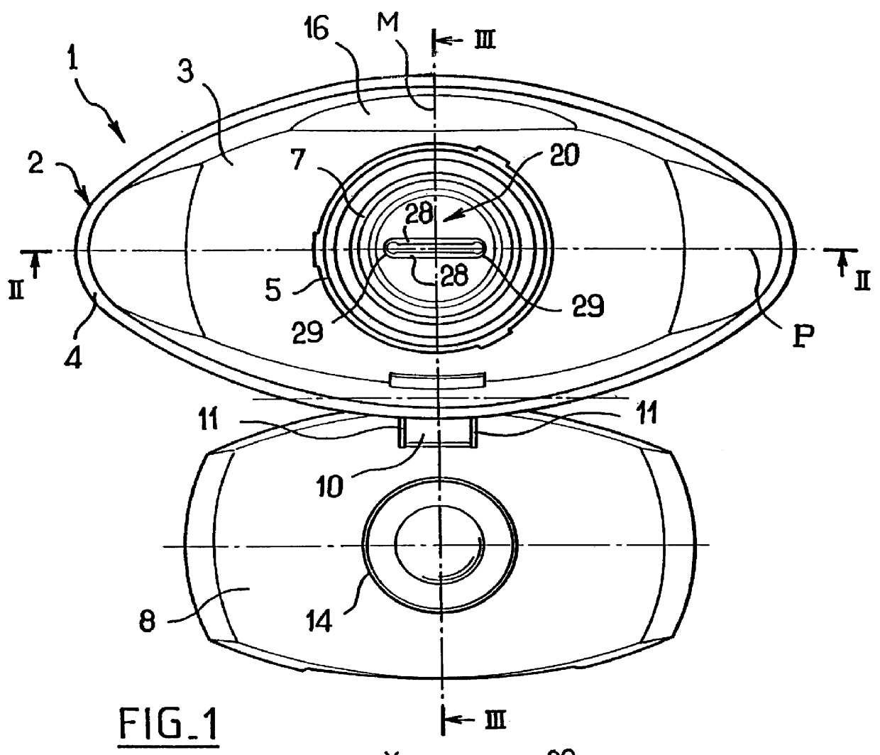
The dispenser head 1 shown in FIGS. 1 to 3 is designed to be fixed on a receptacle, preferably a receptacle having flexible walls, containing a fluid, e.g. a shampoo or a foaming shower gel.

The fluid may present viscosity lying, for example, in the range 0.6 Pa.s to 10 Pa.s.

The dispenser head 1 has a body 2 and a cap 8 capable of pivoting on the body 2 between an open position and a closed position.

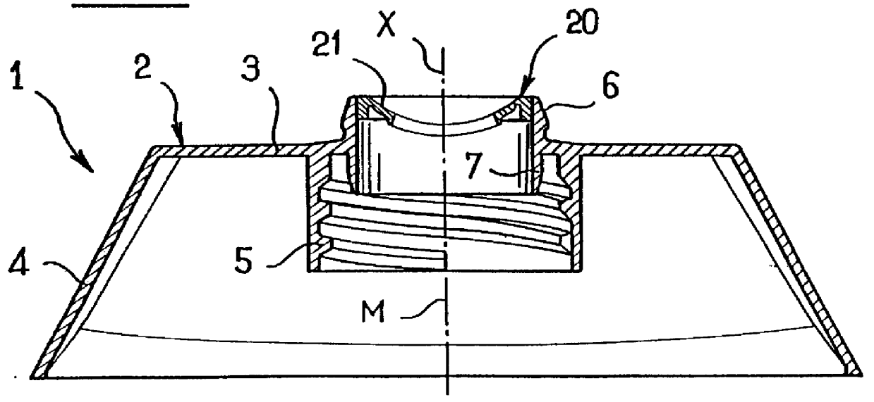
The body 2 has a dispenser endpiece 6 in its top portion, said endpiece 6 being supported by a mounting skirt 5 itself surrounded by an outer skirt 4 of a shape that is adapted to come into register with the wall of the receptacle when the dispenser head 1 is fixed thereon.

The outer skirt 4 is connected to the mounting skirt 5 by a wall 3 which is plane and perpendicular to the axis X, and when seen in plan view is oblong in shape, being elongate in the direction of the pivot axis of the cap 8.

In the example shown, the receptacle has a neck with an outside thread and the mounting skirt 5 ...


PUM

PropertyMeasurementUnit
open widthaaaaaaaaaa
angleaaaaaaaaaa
viscosityaaaaaaaaaa

Abstract

A dispenser head for dispensing a fluid includes a dispenser endpiece of rigid or semi-rigid thermoplastic material and a flow reducer member of elastically deformable thermoplastic material secured to the endpiece. The member includes at least one slot whose edges are suitable for moving apart under the effect of thrust from the fluid while it is being dispensed. A method of making the dispenser head includes making the flow reducer member by injection molding from one or more injection points situated on one or both sides of the slot.

Description

The present invention relates to dispensing a fluid, e.g. a cosmetic or a foodstuff.The invention relates more particularly to a dispenser head having an endpiece of rigid or semi-rigid plastics material and a flow reducer member of elastically deformable plastics material secured to the endpiece.British patent GB-1 046 518 or German utility model DE 29508151 disclose a dispenser head for a receptacle having a flexible wall, the head comprising a rigid endpiece surmounted by a closure membrane made of rubber or of elastomer and provided with a slot made by cutting through the membrane and having edges that touch each other at rest.When the user exerts pressure on the wall of the receptacle, the edges of the slot move apart under thrust from the fluid.That kind of dispenser head does not make it easy to measure out the fluid.To extract fluids, the user must press hard against the wall of the receptacle and, when the slot opens, the fluid is dispensed suddenly.The user can then be sur...

Claims


Application Information

Patent Timeline
Patent Type & Authority Patents(United States)
IPC IPC(8): B29C45/00B29C45/16A45D34/00B65D47/06B65D47/20
CPCB29C45/1676B29C45/0046
Inventor BAUDIN, GILLES
Owner LOREAL SA
Why Eureka
Try Eureka