Centrifugal separator having a chamber with a deformable wall portion

a centrifuge and wall portion technology, which is applied in the direction of centrifuges, rotary centrifuges, etc., can solve the problems of affecting the operation of the centrifugal separator, the rotor of the centrifuge may oscillate, and the pipe member may have severe consequences on the edge of the end wall portion and the pipe member

Inactive Publication Date: 2000-12-19
ALFA LAVAL AB
View PDF6 Cites 26 Cited by
  • Summary
  • Abstract
  • Description
  • Claims
  • Application Information

AI Technical Summary

Problems solved by technology

During operation of such a centrifugal separator, the centrifuge rotor may oscillate.
Such oscillating may arise when the rotor reaches or passes a critical number of revolutions or may be the result of small imbalances of the centrifuge rotor due to, for instance, an uneven distribution of the material within the rotor.
Such a contact between said edge of the end wall portion and the pipe member may have severe consequences to the operation of the centrifugal separator.
Due to the high rotational speed of the centrifuge rotor, the high kinetic energy may deform the end wall portion and the pipe member and damage the rotor, and in a worse case cause a complete breakdown of the operation of the centrifugal separator.
Furthermore, the forces developed by such a hit have a negative impact on the interior elements of the rotor.
However, an increase of the size of the clearance gap means that the position of the surface level of the liquid collected in the chamber is displaced radially outwardly, which influences negatively the function of a paring disc connected to the pipe member, and which also might force the inlet surface level of the liquid in the interior of the rotor radially outwardly.
In addition, such a displacement of the surface level in the collecting chamber increases the effect consumption.
Furthermore, a large clearance gap increases the risk that the separated product is flowing out of the centrifuge rotor in an uncontrolled manner over the radial inner edge of the end wall portion.

Method used


Image

  • Centrifugal separator having a chamber with a deformable wall portion
  • Centrifugal separator having a chamber with a deformable wall portion
  • Centrifugal separator having a chamber with a deformable wall portion

Examples


Embodiment Construction

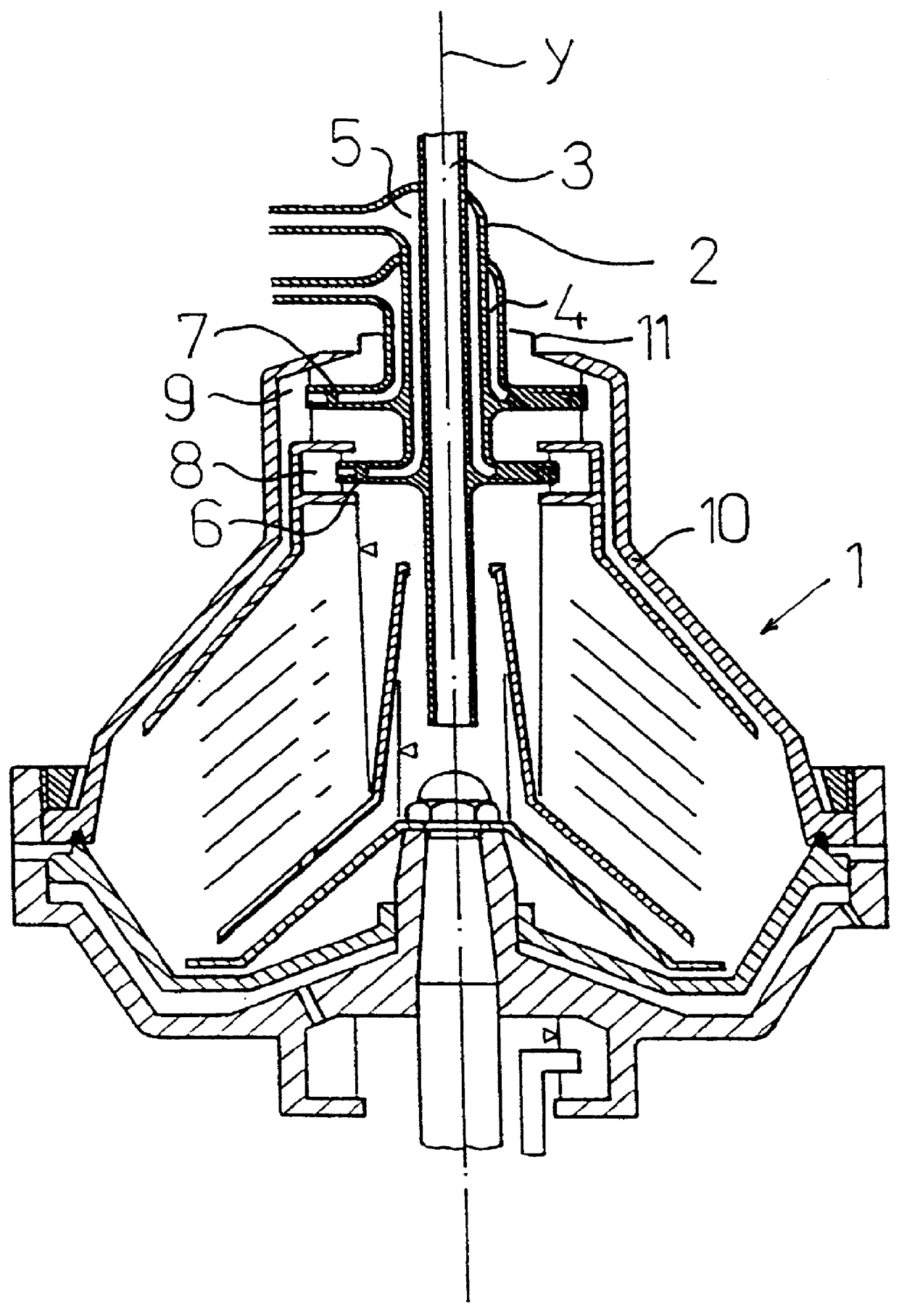
FIG. 1 discloses schematically a centrifuge rotor intended to form a part of a centrifugal separator. A pipe member 2 of the centrifugal separator extends into the interior of the centrifuge rotor 1 through an aperture of the centrifuge rotor 1. The pipe member 2 comprises, in the embodiment disclosed, an inlet passage 3 for the supply of material to be separated to the centrifuge rotor 1 and two outlet passages 4, 5 for the discharge of a respective separated product from the centrifuge rotor 1. Each of the discharge outlet passages 4, 5 is connected to a paring disc 6 and 7, respectively, which extend essentially radially into a lower collecting chamber 8 and an upper collecting chamber 9, respectively, in which the respective separated product is collected during the operation of the centrifugal separator and forms a rotating liquid body having a radially inwardly facing free liquid surface.

In the embodiment disclosed, the pipe member 2 is stationary and the centrifuge rotor 1 is...


PUM


Abstract

A centrifugal separator comprises a centrifuge rotor (1), which has a wall (10) defining an interior of the rotor (1) and which during operation of the centrifugal separator is rotatable about a rotational axis (y) with respect to a stationary pipe member (2) comprising at least one passage for the transport of material. The pipe member (2) is provided to extend into the interior of the centrifuge rotor through an aperture of the rotor (1). A product separated during operation is collected in a chamber (9) provided in the proximity of said aperture and partly defined by an end wall portion (11) extending around said aperture and the pipe member (2) in such a manner that a clearance gap is formed between a radially inner edge of the end wall portion (11) and the pipe member (2). The end wall portion (11) is arranged to be deformable in the case that the pipe member contacts the end wall portion during the operation of the separator.

Description

THE BACKGROUND OF THE INVENTION AND PRIOR ARTThe present invention refers to a centrifugal separator comprising a centrifuge rotor, which has a wall defining an interior of the rotor and which during operation of the centrifugal separator is rotatable about a rotational axis with respect to a stationary pipe member comprising at least one passage for the transport of material, the stationary pipe member being provided to extend into the interior of the centrifuge rotor through an aperture of the rotor, and a chamber provided in the proximity of said aperture to collect a product separated during operation, the chamber being partly defined by an end wall portion, extending around the aperture and the pipe member in such a manner that a clearance gap is formed between a radially inner edge of the end wall portion and the pipe member.The separated product collected in the chamber forms a rotating liquid body having a radially inwardly facing free liquid surface located radially outside...

Claims


Application Information

Patent Timeline
Patent Type & Authority Patents(United States)
IPC IPC(8): B04B7/00B04B7/08B04B1/00B04B1/08
CPCB04B7/08B04B1/08
Inventor KARLSSON, PER GUNNAR
Owner ALFA LAVAL AB
Why Eureka
Try Eureka