Non-contact surface roughness measuring device

Inactive Publication Date: 2000-12-26
MITUTOYO CORP
View PDF12 Cites 43 Cited by
  • Summary
  • Abstract
  • Description
  • Claims
  • Application Information

AI Technical Summary

Problems solved by technology

However, the following disadvantages occur by simply attaching the non-contact surface roughness probe to the coordinate measuring machine.
However, the coordinate measuring machine cannot recognize the position of the detection surface, therefore, calibration is extremely difficult.
2 Since the non-contact surface roughness probe is made to detect only roughness, even when the

Method used


Image

  • Non-contact surface roughness measuring device
  • Non-contact surface roughness measuring device
  • Non-contact surface roughness measuring device

Examples


Embodiment Construction

A preferred embodiment of the present invention will be described below with reference to the attached drawings.

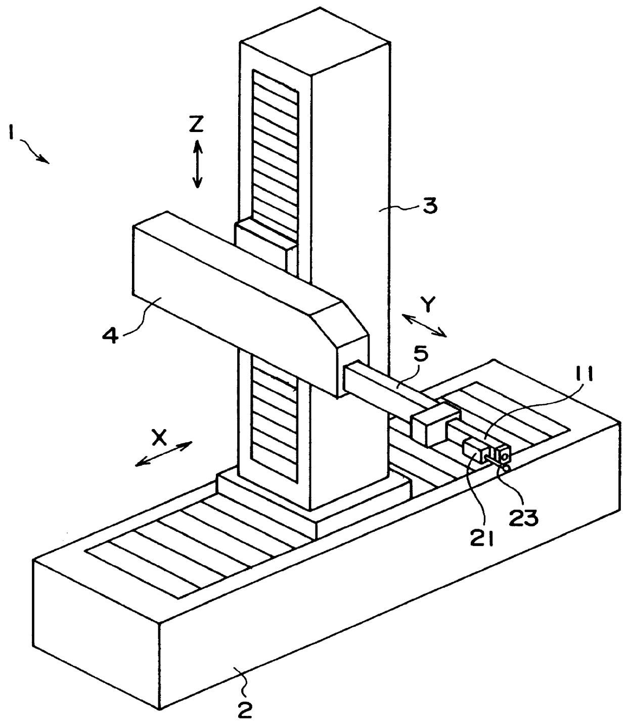
FIG. 1 is a perspective view showing a measurement device according to the present embodiment. The measuring device has a coordinate measuring machine 1 as a moving mechanism. The coordinate measuring machine 1 has a base 2, a column 3 provided on the base 2 to be movable in a longitudinal direction of the base 2 (X-axis direction), a slider 4 provided on the column 3 to be elevatable up and down (in Z-axis direction) and an arm 5 provided on the slider 4 to be movable back and forth (in Y-axis direction).

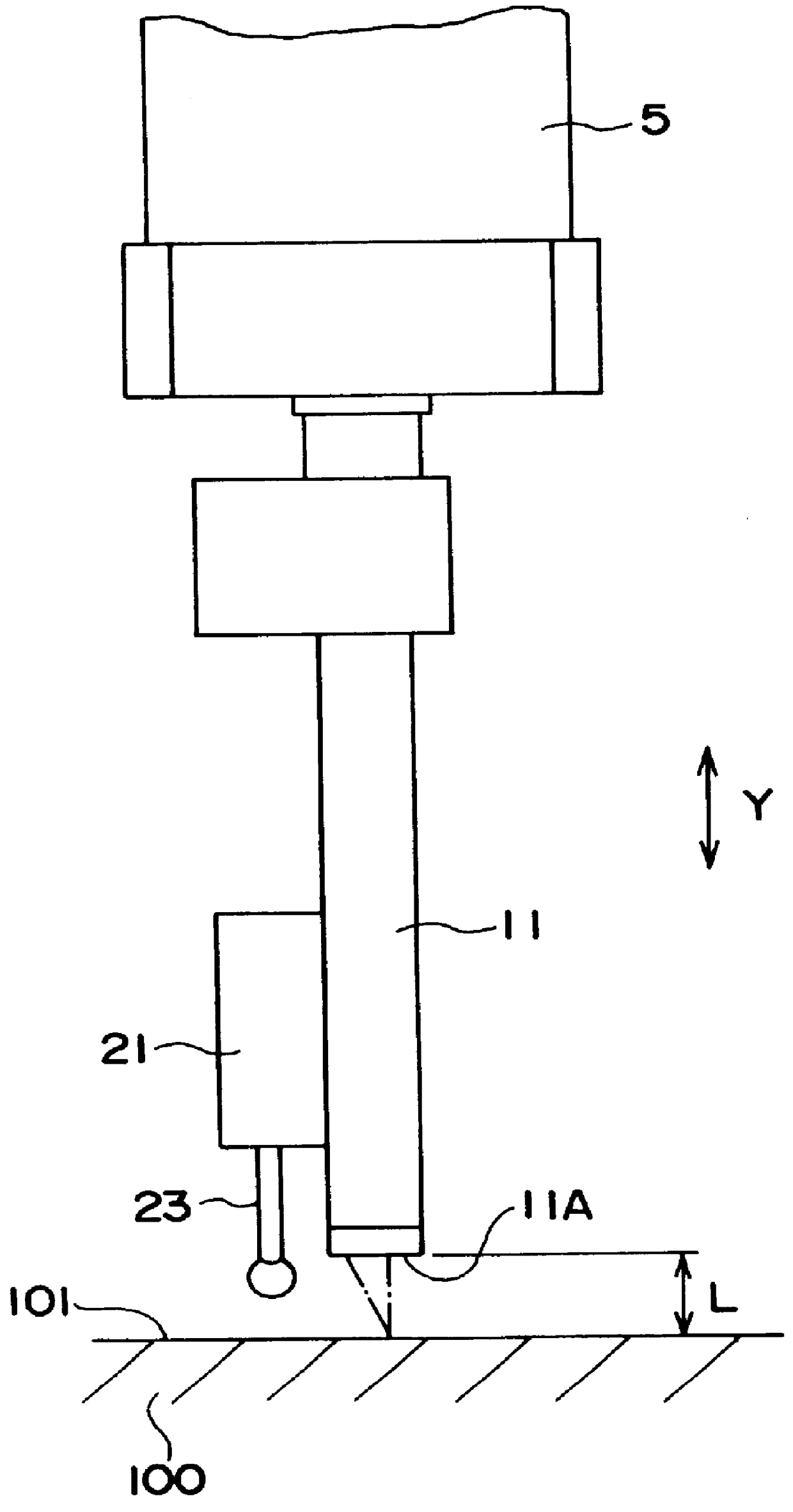
At the tip end of the arm 5, in other words, at the pointed end section of the arm 5 as a movable section which can be moved in X,Y and Z-axis direction orthogonal with each other, a non-contact surface roughness probe 11 for non-contactly measuring a surface roughness of a measurement surface 101 of a workpiece 100 is attached as shown in FIG. 2. A touch-signal probe 21 ...


PUM


Abstract

A non-contact surface roughness-measuring machine is provided which can avoid damage caused by collision with a workpiece and set a non-contact surface roughness probe at an appropriate position relative to a measurement surface of the workpiece. A non-contact surface roughness probe and a touch-signal probe are attached at a tip end of an arm of a coordinate measuring machine. A stylus of the touch-signal probe is protruded relative to a detection surface of the non-contact surface roughness probe, in which the protrusion amount is within an optimum distance of the non-contact surface roughness probe relative to the measurement surface. When the probes are brought close to the workpiece and the touch-signal probe detects contact, the non-contact surface roughness probe is set within the optimum distance relative to the workpiece.

Description

1. Field of the InventionThe present invention relates to a non-contact surface roughness-measuring device. More specifically, the present invention relates to a non-contact surface roughness-measuring device which measures a surface roughness of a measurement surface of a workpiece without contacting thereto employing a coordinate measuring machine.2. Description of Related ArtA contact-type surface roughness-measuring device of which a stylus is abutted to the measurement surface of the workpiece and moved thereon, thereby detecting a displacement of the stylus as an electric signal and measuring a surface roughness of the measurement surface by processing the electric signal is conventionally known as a surface roughness-measuring device for measuring a surface roughness of a measurement surface of a workpiece. Also, a non-contact surface roughness-measuring device, in which a laser beam is irradiated to the measurement surface of the workpiece thereby measuring the surface rough...

Claims


Application Information

Patent Timeline
IPC IPC(8): G01B11/30G01B21/02G01B21/04G01B7/00G01B21/00G01B21/30
CPCG01B21/047G01B11/303
Inventor MATSUMIYA, SADAYUKIARAI, MASANORINAKAZAWA, NOBUYUKI
Owner MITUTOYO CORP
Why Eureka
Try Eureka