Method of measuring a pressure of a pressurized fluid fed through a diaphragm pump and accumulated in a vessel, and miniature pump system effecting the measurement

Inactive Publication Date: 2000-12-26
MATSUSHITA ELECTRIC WORKS LTD
View PDF8 Cites 97 Cited by
  • Summary
  • Abstract
  • Description
  • Claims
  • Application Information

AI Technical Summary

Problems solved by technology

However, the addition of the separate pressure sensor in or around the vessel gives an addi

Method used


Image

  • Method of measuring a pressure of a pressurized fluid fed through a diaphragm pump and accumulated in a vessel, and miniature pump system effecting the measurement
  • Method of measuring a pressure of a pressurized fluid fed through a diaphragm pump and accumulated in a vessel, and miniature pump system effecting the measurement
  • Method of measuring a pressure of a pressurized fluid fed through a diaphragm pump and accumulated in a vessel, and miniature pump system effecting the measurement

Examples


Embodiment Construction

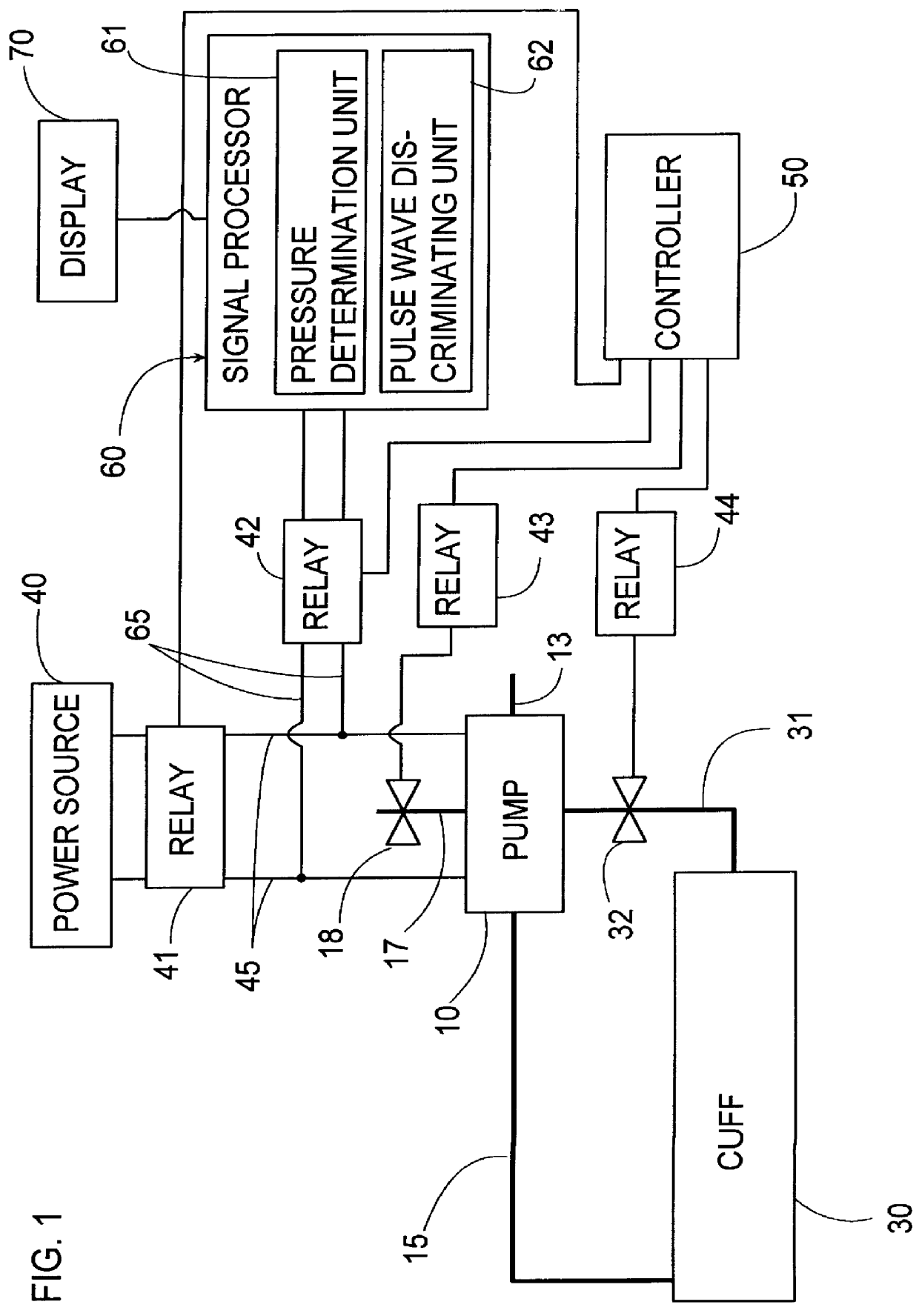
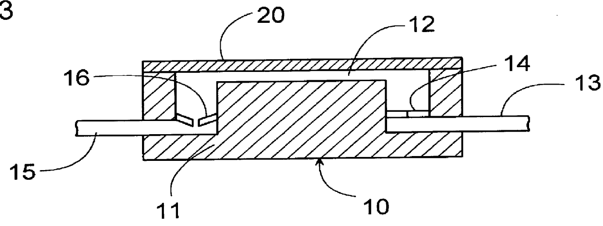
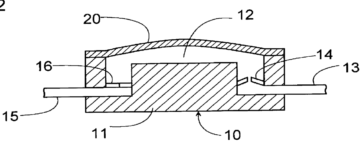
Referring now to FIGS. 1 to 4, there is shown a pump system in accordance with a first embodiment of the present invention. The pump system is adapted for measurement of a blood pressure and includes a diaphragm pump 10, a cuff 30 for occluding an artery of a human body, and an electronics for controlling the pump. The pump 10 draws in an outside air through an inlet path 13 and feed it through an outlet path 15 to accumulate a pressurized air in the cuff 30 or vessel. As shown in FIGS. 2 to 4, the pump 10 has a diaphragm 20 which is made of a piezoelectric element, for example, PZT and defines a pump cavity 12 between the pump casing 11 and the diaphragm. The diaphragm 20 is formed on opposite faces thereof with driving electrodes 21 and 22. A power source 40 is connected to apply a DC pulse voltage through a relay 41 across the electrodes 21 and 22, causing the diaphragm to deflect or displace repeatedly, thereby drawing the air through an inlet valve 14 and feeding it to the cuff...


PUM


Abstract

A method and system for determination of a pressure of the pressurized fluid with the use of a diaphragm pump responsible for accumulating the pressurized fluid in the vessel. The pump has a pump cavity and a diaphragm with a piezoelectric element which is actuated by an application of a voltage to displace the diaphragm for pumping a fluid into the vessel. The method comprises the steps of: (a) deactivating the diaphragm by removal of the voltage to the piezoelectric element so as to stop pumping the fluid and accumulating the pressurized fluid into the vessel; (b) introducing the pressurized fluid only from the vessel back into the pump cavity so as to cause a displacement of the diaphragm by the pressurized fluid; (c) deriving an electrical signal indicative of the displacement of the diaphragm; and (d) translating the electrical signal into a corresponding pressure value indicative of the pressure of the pressurized fluid in the vessel.

Description

1. Field of the InventionThe present invention is directed to a method of measuring a pressure of a pressurized fluid fed through a diaphragm pump and accumulated in a vessel, and a miniature pump system for in situ measurement of the pressure within the pump.2. Description of the Prior ArtDiaphragm pumps are well known in the art. Specifically, the pump utilizing a piezoelectric element for actuating a diaphragm has been proposed for miniaturization of the pump. When sensing the pressure of a pressurized fluid developed by the pump and accumulated in a vessel, a separate pressure sensor needs to be provided on the side of the vessel. However, the addition of the separate pressure sensor in or around the vessel gives an additional bulk to a pump system, which is a hindrance to a miniaturization of the pump system.The present invention has been achieved in view of the above problem, and has therefore a primary object of providing a method and a system which are capable of measuring t...

Claims


Application Information

Patent Timeline
IPC IPC(8): A61B5/022A61B5/0235F04B43/02F04B43/04F04B17/00G01L9/00
CPCA61B5/0235G01L9/008F04B43/046F04B17/003
Inventor TANI, MICHIHIKOMASAKI, YASUFUMI
Owner MATSUSHITA ELECTRIC WORKS LTD
Why Eureka
Try Eureka