Optical display device having prismatic film for enhanced viewing

a technology of optical display and prismatic film, applied in the field of optical display devices, can solve the problems of back-lighted displays consuming more power than reflective displays, back-lighted displays are large and heavier, and back-lighted displays have significant disadvantages for use in portable electronic products, so as to improve the visibility of the display, reduce the glare, and increase the legibility of the display

Inactive Publication Date: 2000-12-26
GOOGLE TECH HLDG LLC
View PDF39 Cites 98 Cited by
  • Summary
  • Abstract
  • Description
  • Claims
  • Application Information

AI Technical Summary

Benefits of technology

The difference in the incident angle with respect to the primary exiting angle improves visibility of the display by steering exiting light into a preferential viewing cone or preferred viewing angle. The preferential viewing cone or angle contains the primary exiting light at the exiting angle. The preferential viewing cone is defined by a conical region about the normal axis. The preferential viewing cone optimally encompasses the conical region from approximately zero to ten degrees relative to the normal axis. Therefore, the prismatic film may reduce the glare and increase the legibility of the display, which is illuminated by ambient light.

Problems solved by technology

Back-lighted displays consume more power than reflective displays do.
In addition, back-lighted displays are larger and heavier than reflective displays.
Thus, back-lighted displays have significant disadvantages for use in portable electronic products.
Reflective displays are susceptible to the negative influence of glare that is typically attendant with the ambient light illuminating the display.
The glare greatly reduces the effectiveness of the display by reducing the contrast between inactive and active pixels.
Even the light initially transmitted through the viewing plane may contribute to the glare perceived by a user.
Such refractive interfaces can reflect some incident light toward the viewing plane and the viewer, reducing the effectiveness of the display.
Multiple-layer holographic filters may be achromatic, but the thickness and additional cost over single layer holographic filters have limited commercial use of the multiple-layer holographic filters.

Method used


Image

  • Optical display device having prismatic film for enhanced viewing
  • Optical display device having prismatic film for enhanced viewing
  • Optical display device having prismatic film for enhanced viewing

Examples


Embodiment Construction

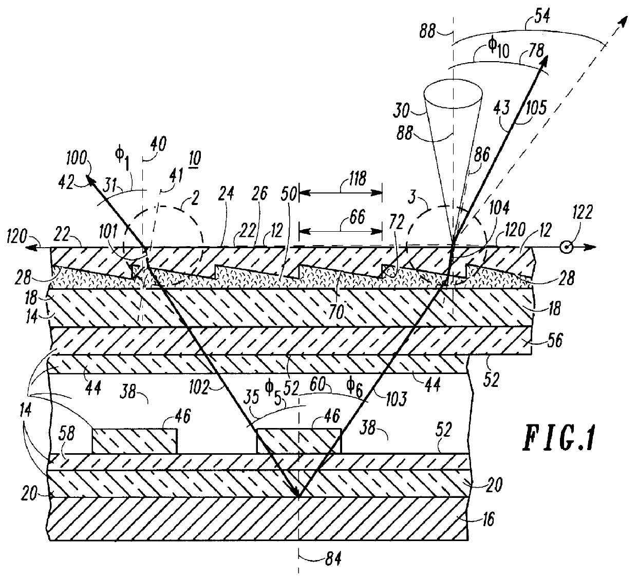
The present invention is best understood by first defining various terms used throughout the specification. As used herein, "optically coupled" refers to elements in optical communication with each other that permit the bi-directional transmission of light in at least one plane.

The viewing plane 26 refers to an imaginary flat surface defined by a mathematical plane substantially parallel to the cell front 56. In practice, the viewing plane 26 may be coincident with a lens of the display. The viewer views the display by looking toward or into the viewing plane 26.

As used herein, light shall refer to a group of light rays represented by a representative ray. The representative ray represents the general direction of propagation of an illustrative group of light rays. For example, the direction of propagation of incident light 42 may be represented by a representative ray. In FIG. 1, the representative ray is divided into a first section 100, a second section 101, a third section 102, ...


PUM

PropertyMeasurementUnit
incident angleaaaaaaaaaa
exiting angleaaaaaaaaaa

Abstract

The display device includes an optical cell having a cell front with at least one cell region being capable of an optically transmissive mode and an optically nontransmissive mode with reference to the cell front. The optical cell contains an optically active material responsive to an applied electrical field such that optical properties of the material are controllably changeable. A reflector may be optically coupled to the cell. A prismatic film including a prismatic surface is optically coupled to the optical cell. The prismatic surface preferably comprises a series of prisms. The prisms have first faces and second faces intersecting the first faces. The first faces are oriented to refract light obliquely intercepting the first faces and the second faces are oriented to minimize refractive, reflective, and optical interactions of the light with the second faces. The prismatic film, the cell, and the reflector optically cooperate such that light entering a display at an incident angle is emitted from the display at an exiting angle distinct from the incident angle for viewing of the display.

Description

The present invention relates generally to an optical display device. More particularly, the present invention relates to a reflective, optical display device having a prismatic film to enhance a viewer's perceived brightness of the display in a preferred viewing cone.Prior-art optical displays include back-lighted liquid crystal displays and reflective liquid crystal displays. Back-lighted displays consume more power than reflective displays do. In addition, back-lighted displays are larger and heavier than reflective displays. Thus, back-lighted displays have significant disadvantages for use in portable electronic products.Reflective displays rely on ambient light to illuminate the pixels, symbols, or characters of the displays. Reflective displays are susceptible to the negative influence of glare that is typically attendant with the ambient light illuminating the display. As used herein, glare or glare light rays refer to an unwanted reflection of incident ambient light off any...

Claims


Application Information

Patent Timeline
Patent Type & Authority Patents(United States)
IPC IPC(8): G02B1/11G02B1/10G02B5/04G02F1/13G02F1/1335G02B27/00
CPCG02B1/11G02B5/045G02F1/133504G02F1/133526G02F2203/22G02F1/133502
Inventor AKINS, ROBERT BENJAMINVALLIATH, GEORGE THOMASJELLEY, KEVIN WILLIAM
Owner GOOGLE TECH HLDG LLC
Why Eureka
Try Eureka