Ink jet recording apparatus

a recording apparatus and jet head technology, applied in the field of jet head, can solve the problems of affecting the quality and reliability of printed materials, affecting the quality of printed materials, so as to reduce the overall anode bonding processing time, improve the reliability, and reduce the time used to heat

Inactive Publication Date: 2001-01-02
SEIKO EPSON CORP
View PDF49 Cites 32 Cited by
  • Summary
  • Abstract
  • Description
  • Claims
  • Application Information

AI Technical Summary

Benefits of technology

According to the twenty-second embodiment, three substrates 100, 200 and 300 are simultaneously anode-bonded to each other. The middle substrate 200 is of silicon, and the second and upper substrates, 200 and 300, are boro-silicated. The upper substrate 100 functions merely as a lid for nozzle holes 400, emitting chamber 600, orifice 700 and ink cavity 800. The bond between the upper 100 and middle 200 substrates is consequently less critical, so soda glass may be substituted for boro-silicated with respect to upper substrate 100. However, when the upper substrate is made of boro-silicated glass, it is possible to improve its reliability.
In accordance with the twenty-second embodiment, upper and lower joining electrode plates 111 and 112 to be contacted with the lower and upper bo...

Problems solved by technology

When an electrical pulse is applied between a diaphragm and electrode, the resulting electrostatic force deforms the diaphragm, causing an ink droplet to be ejected from the nozzle.
However, when this is done, the air sealed inside the ejection chamber works as a resistance to the electrostatic attraction of the diaphragm, thus inhibiting normal operation by preventing sufficient electrostatic attraction.
When the elec...

Method used


Image

  • Ink jet recording apparatus
  • Ink jet recording apparatus
  • Ink jet recording apparatus

Examples


Embodiment Construction

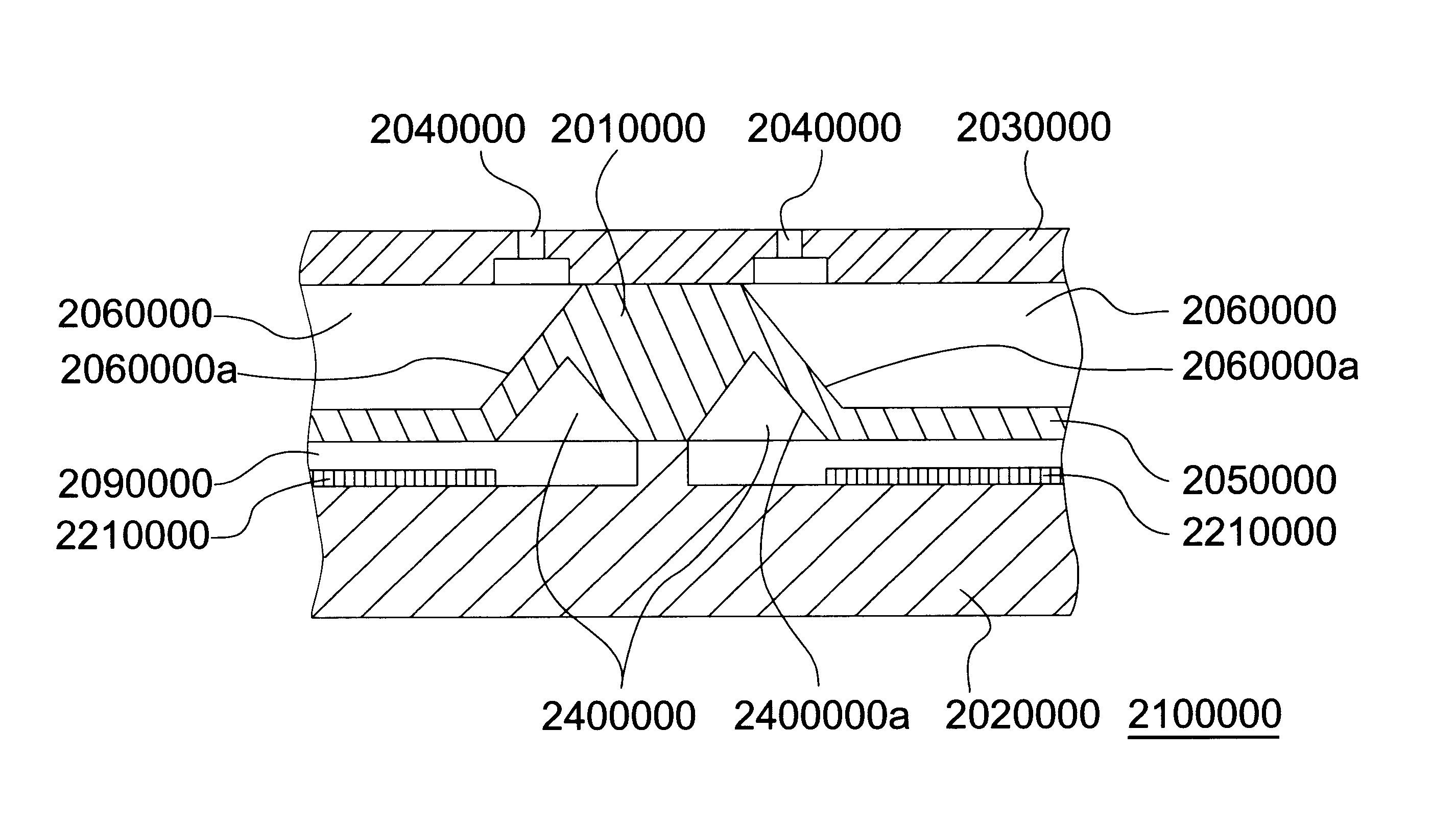
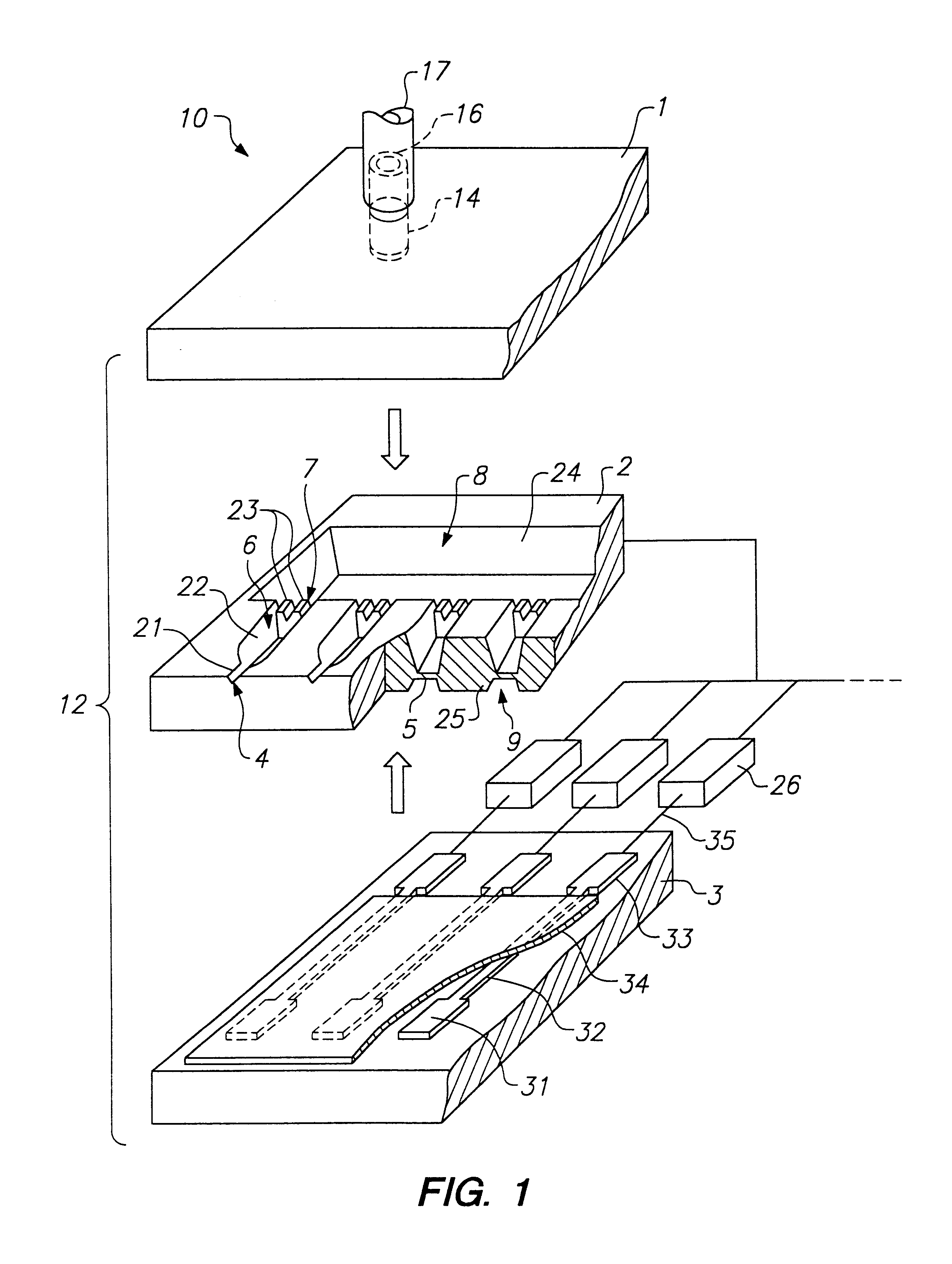
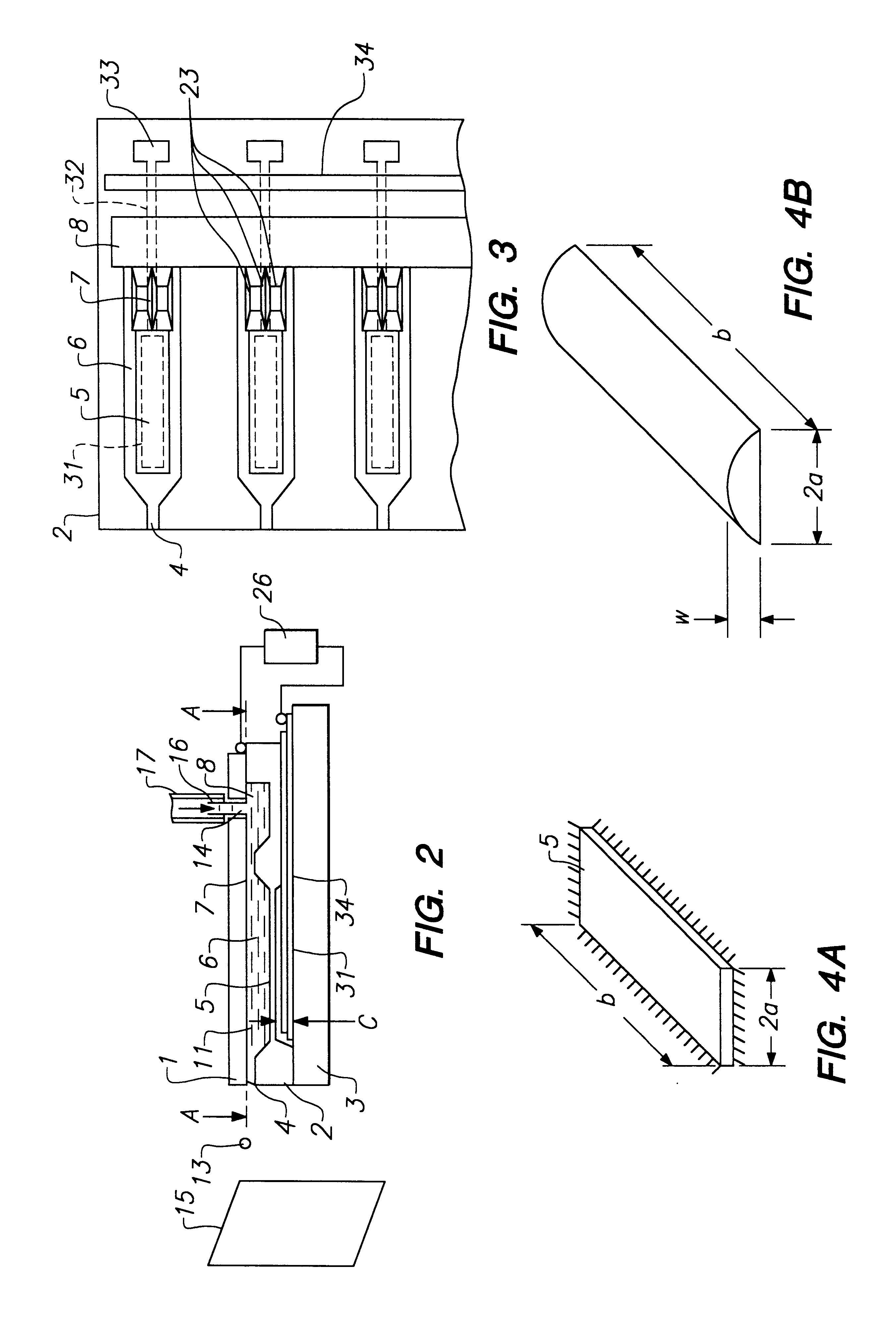
FIG. 59 is a partly exploded perspective view partly in section of an ink jet head according to a presently preferred embodiment of the present invention. FIG. 60 is an enlarged view of part A in FIG. 59. FIG. 61 is a perspective view of the ink jet head shown in FIG. 59 after assembly. FIG. 62 is a side view in section of the ink jet head shown in FIG. 59. FIG. 63 is a section view along line A--A in FIG. 62. It should be here noted that while the presently preferred embodiment is described below with reference to an edge eject type ink jet head in which ink droplets are ejected from nozzle holes disposed along a substrate edge, the invention shall obviously not be limited thereto and can also be applied to a face eject type ink jet head in which ink droplets are ejected from nozzle holes disposed on a top face of a substrate. As will be known from FIG. 59, an ink jet head 100000 according to the present embodiment has a lamination structure in which three substrates 10000, 20000, ...


PUM

PropertyMeasurementUnit
Volumeaaaaaaaaaa
Volumeaaaaaaaaaa
Volumeaaaaaaaaaa

Abstract

An ink jet recording apparatus that achieves sufficient attraction force even when the actuator is sealed. In the ink jet recording apparatus, an electric pulse is applied between a diaphragm and electrode by a drive circuit to deform a diaphragm by electrostatic force to eject an ink droplet from a nozzle comprises a vibration chamber containing a wall surface formed by the diaphragm and a wall surface on which the electrode is formed, and a first cavity communicating with the vibration chamber and containing a wall surface on which is provided a lead for connecting the drive circuit and electrode. The vibration chamber is sealed airtight, and comprises a second cavity communicating with the vibration chamber or first cavity for increasing the volume of the airtight sealed part of the actuator.

Description

1. Field of the InventionThe present invention relates to an ink jet head in which an electrostatic actuator is used as a means for generating pressure to eject an ink droplet, and relates more particularly to sealing the electrostatic actuator.2. Description of the Related ArtOne common type of ink jet head uses the electrostatically induced attraction force generated by an electrostatic actuator as described, for example, in Japanese Unexamined Patent Publication (kokai) Hei2-289351. This type of ink jet head has a nozzle, an ink path communicating with a nozzle, a diaphragm formed in part of the ink path, and an electrode formed in opposition to the diaphragm with an air gap therebetween. When an electrical pulse is applied between a diaphragm and electrode, the resulting electrostatic force deforms the diaphragm, causing an ink droplet to be ejected from the nozzle.In the aforementioned ink jet head, however, the actuator contains a vibration chamber, which comprises a diaphragm...

Claims


Application Information

Patent Timeline
IPC IPC(8): B41J2/14B41J2/16C04B37/04
CPCB41J2/14314B41J2/16B41J2/1623B41J2/1629B41J2/1631B41J2/1632B41J2/1645B41J2/1646B41J2002/14338B41J2002/14379B41J2002/14387B41J2202/03B41J2202/11
Inventor NOJIMA, SHIGEOFUJII, MASAHIROTAKEKOSHI, TAROISHIKAWA, HIROYUKI
Owner SEIKO EPSON CORP
Why Eureka
Try Eureka