Engine lift for outboard motor
- Summary
- Abstract
- Description
- Claims
- Application Information
AI Technical Summary
Benefits of technology
Problems solved by technology
Method used
Image

Examples
Embodiment Construction
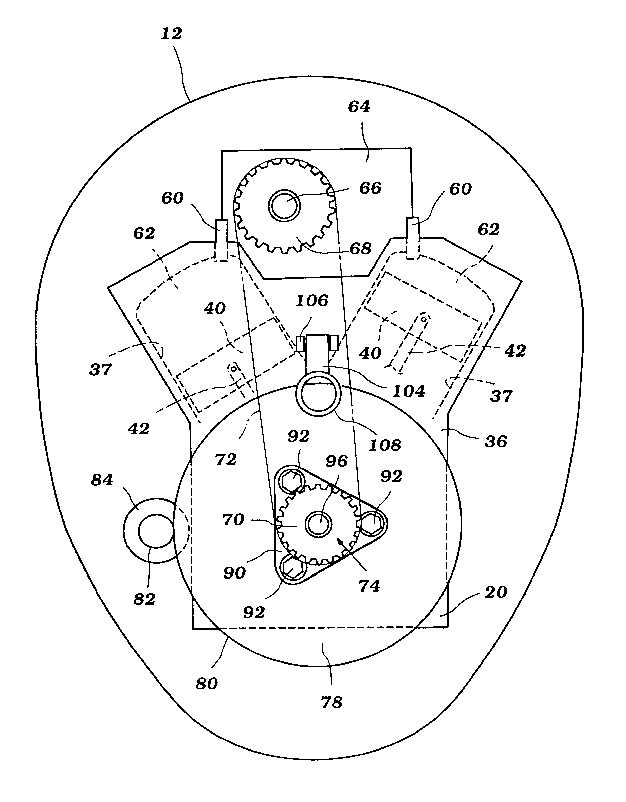
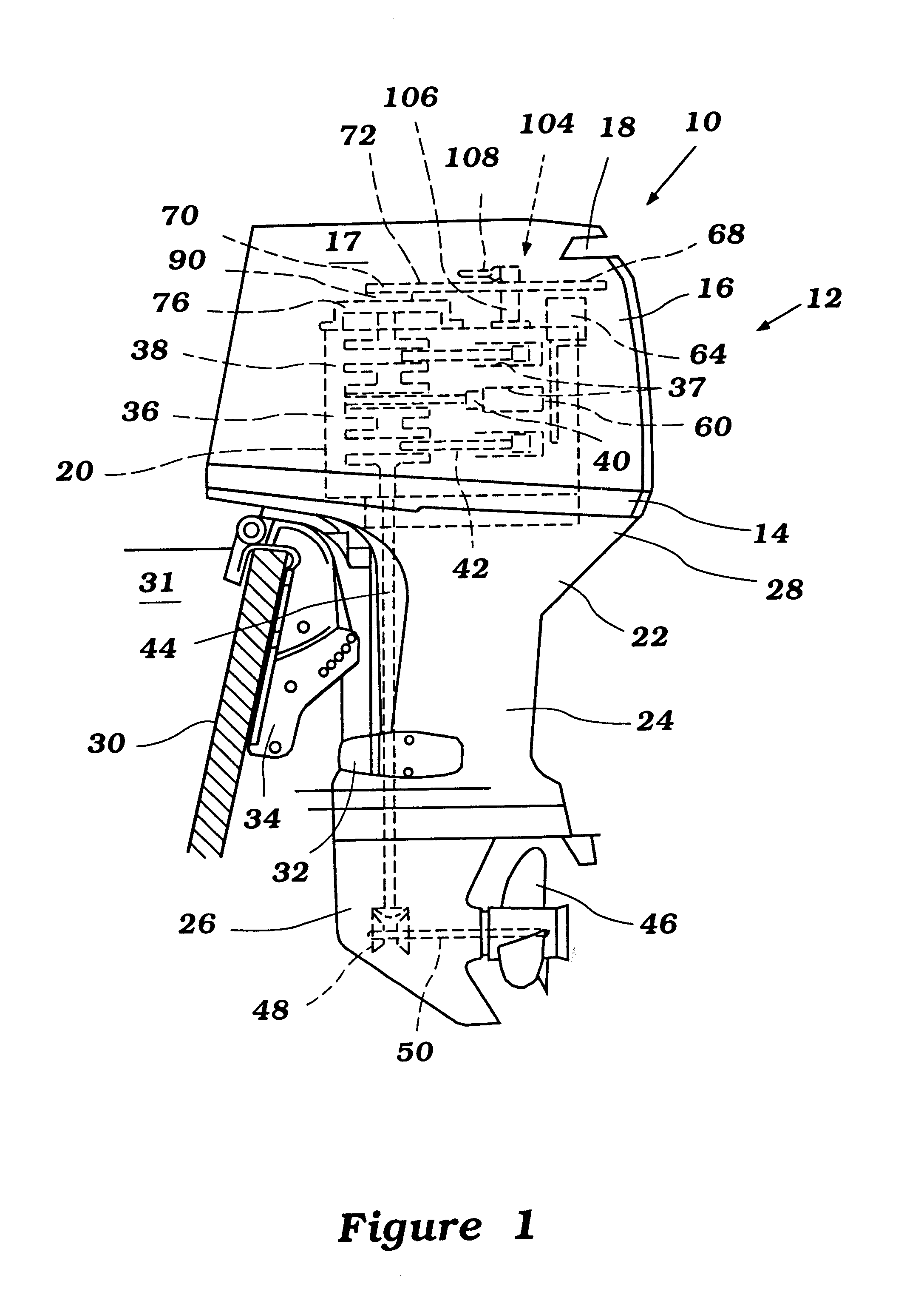
With initial reference to FIG. 1, an outboard motor for powering watercraft is illustrated therein. The outboard motor, indicated generally by the reference numeral 10, advantageously features a lift arrangement having certain features, aspects and advantages of the present invention. The outboard motor 10 provides an exemplary environment in which the present lift arrangement has particular utility. Other environments of use may readily present themselves to individuals having ordinary skill in the relevant arts. The lift assembly includes one or more lifting lug. The term lifting lug as used herein shall refer to any of a number of mechanical arrangements providing a specific component or structure sized and configured specifically for being gripped for lifting. Accordingly, lifting lugs should be construed to include, but not be limited to, curved clutches, dogs, hooks, claws, clasps, curved members, stays, eyelets, eyebolts, rings, t-bolts, and the like.
With continued reference ...
PUM
 Abstract
Description
Claims
Application Information