Water control gate

a technology of water control gate and gate body, which is applied in the direction of coastline protection, marine site engineering, hydroelectric engineering, etc., can solve the problems of prone to failure of more sophisticated gates which are hydraulically or mechanically operated, add significantly to their operating costs, and many water control gates only tend to operate effectively

Inactive Publication Date: 2001-01-09
TOWNSHEND PETER DOUGLAS
View PDF8 Cites 39 Cited by
  • Summary
  • Abstract
  • Description
  • Claims
  • Application Information

AI Technical Summary

Benefits of technology

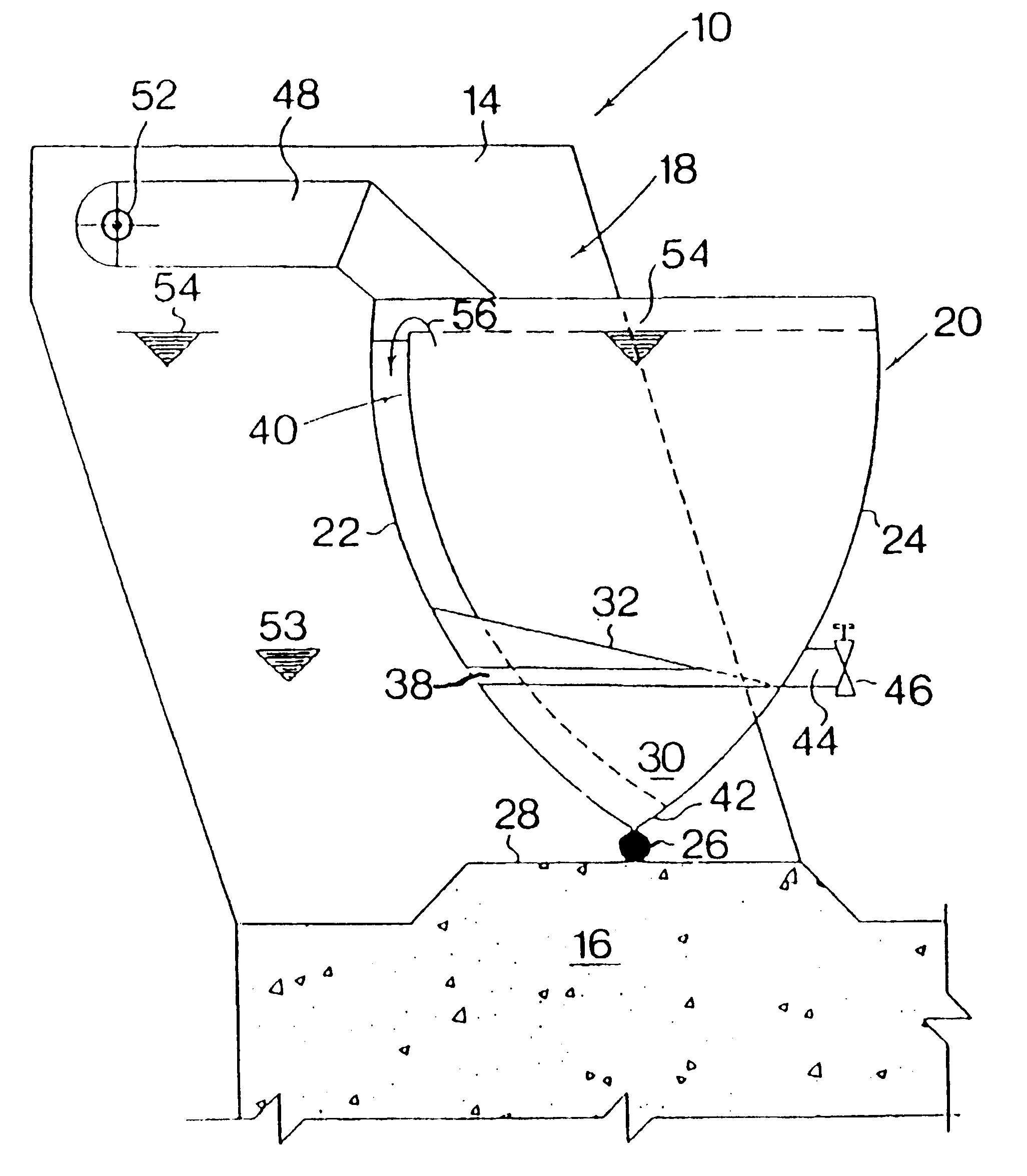
In another form of the invention, in which the water control gate assembly is in the form of a weir scour gate, the downstream outlet may comprise a syphon arrangement which allows for almost complete discharging of the ballast tank after priming of the syphon arrangement so as to cause rapid opening of the gate.
In another form of the invention, a level control canal gate, the downstream outlet is provided with valve means responsive to close the outlet in the event of the downstream water level reaching a predetermined upper level, thereby allowing the ballast tank to fill and to increase the closing moment of the gate. The valve means is further arranged to open the outlet in the event of the downstream water level falling below a predetermined lower level, thereby to increase the opening moment of the gate.

Problems solved by technology

These extend from simple manually operated sluice gates to highly complicated automatic control gates for operating electronically or mechanically operated hydraulic equipment in response to various electronic water level and flow sensors.
Most water control gates require human intervention, which add significantly to their operating costs.
Further, many water control gates only tend to operate effectively under normal flow conditions, and not flood conditions.
More sophisticated gates which are hydraulically or mechanically operated are prone to failure, and require regular maintenance, as well as access to a power source.

Method used


Image

  • Water control gate
  • Water control gate
  • Water control gate

Examples


first embodiment

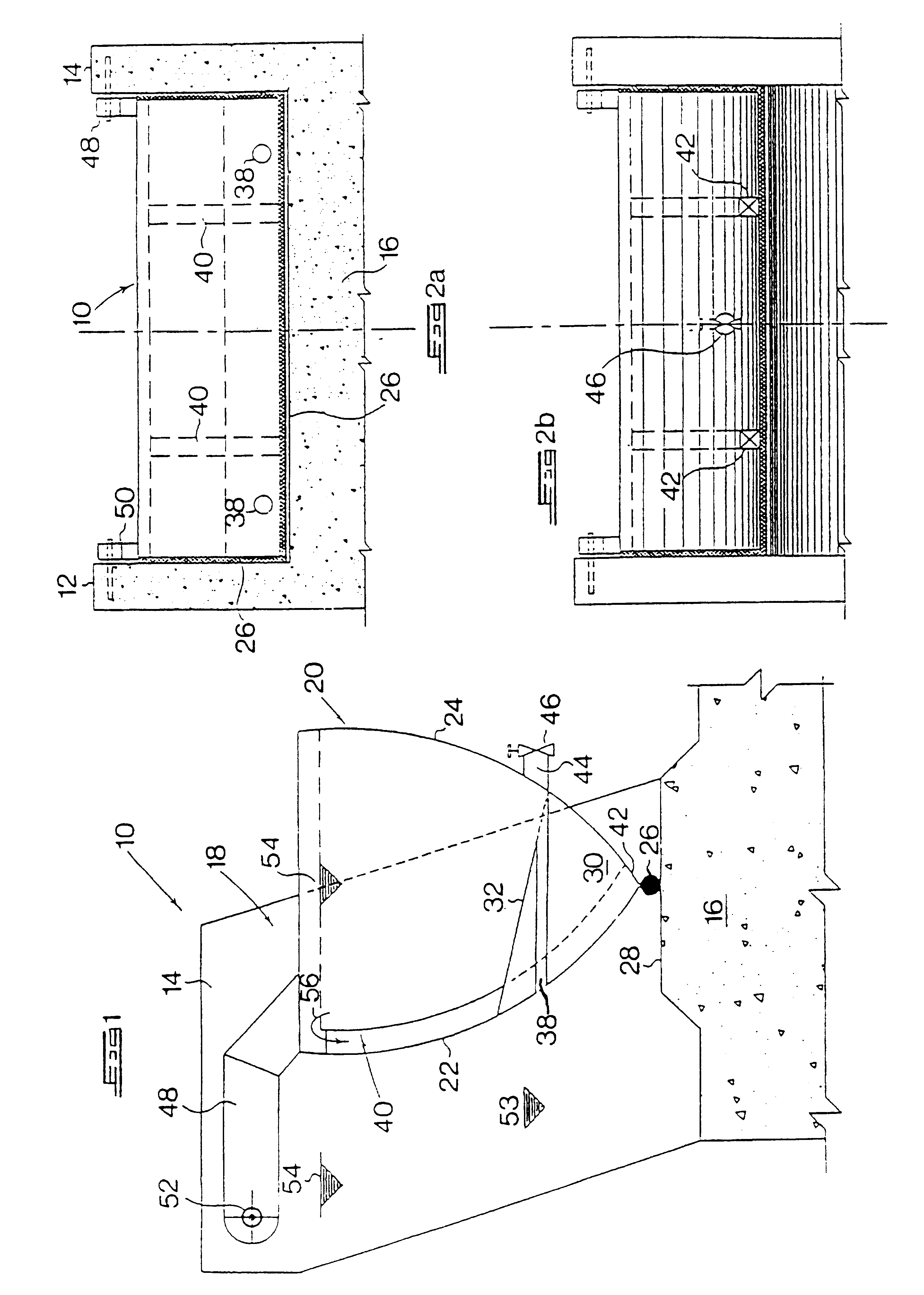
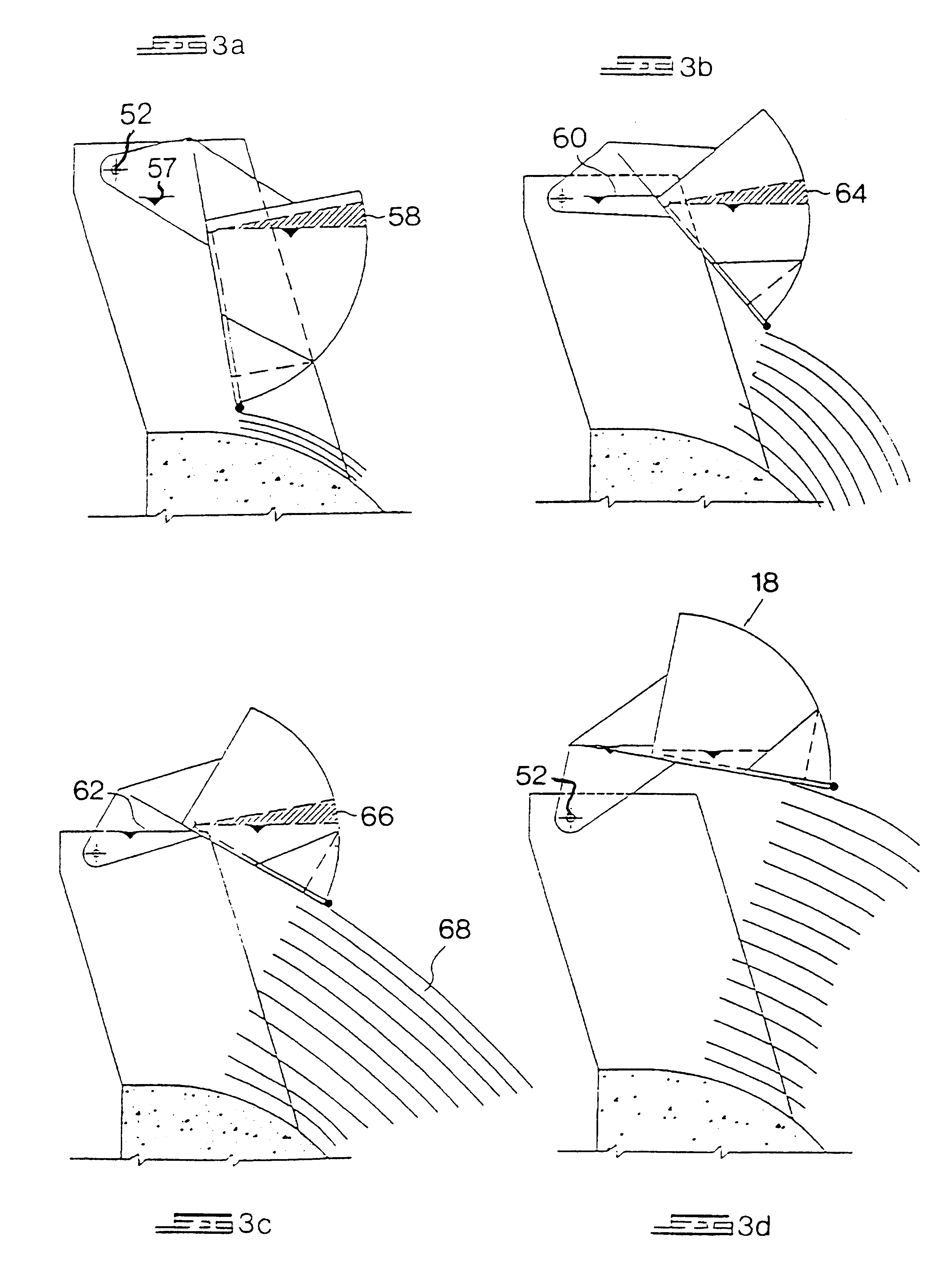
Referring first to FIGS. 1 to 2B, a water control gate assembly 10 comprises a pair of piers 12 and 14 which extend upwardly from an outlet structure such as a dam spillway 16. A top-hung gate 18 includes a ballast tank 20 formed with opposed convex upstream and downstream walls 22 and 24. An elongate seal element 26 is fitted to the base and sides of the gate at the confluence of the walls, and is arranged to provide a seal between the gate and the top surface 28 of the spillway 16, as well as against the sides of the piers 12 and 14. The top-hung gate includes a lower void portion or buoyancy tank 30 which is separated from the ballast tank by means of a dividing wall 32 which slopes downwardly from the upstream wall 22 to the downstream wall 24 at an angle of depression of approximately 45.degree.. The ballast tank 20 is formed with a pair of spaced apart upstream water inlet pipes 38 and a pair of outlet launders 40 which extend from near the top of the upstream wall 22 to an ou...

second embodiment

Referring now to FIG. 4, a top-hung gate in the form of a spillway crest gate 72 is shown. The object of such a gate is to retain a body of water at a required full supply level above a fixed spillway or outlet structure in a dam or weir, thereby increasing the storage capacity thereof.

A one-way flap valve 73 is located at the outlet of the inlet opening 38 at the point where the inlet opening vents into the ballast tank 20. The flap valve 73 is arranged to pivot upwardly to a position indicated in broken outline at 73A on the ingress of water via the inlet opening 38, and is similarly arranged to close in the event of water flowing in the opposite direction from the ballast tank 20. In the event of wave action acting against the downstream wall 22 of the gate, the flap valve 73 will tend to open as the crest of the wave reaches the gate in response to the high hydrostatic forces acting on it, thereby causing water to flow into the ballast tank. However, as the trough of the wave mo...

fifth embodiment

Referring now to FIGS. 14A and 14B, a top-hung gate in the form of a tidal control gate 240 is shown. This gate is designed to allow inland water to flow out to sea when the sea level is below the inland water level, and to close off the gate to prevent tidal sea water from flowing inland when the sea level is at a predetermined level above the inland water level. In FIG. 14A. the inland water level 242 is higher than the water level 244 on the seaward side, thereby causing water to decant through the outlet launder 230 and allowing inland water to flow out to sea.

In FIG. 14B, the sea water level 246 is higher than the inland water level 248. A seal in the form of a flexible plate 250 extends from the base of the gate. This plate serves as a reaction plate which causes a downward drag on the gate as water flows from the seaward side of the gate. The plate 250 also serves as a guide to guide water back up the outlet launder 230 into the ballast tank 252 in the direction of arrow 254....


PUM


Abstract

A water control gate assembly comprises a self-actuating top-hung gate for controlling the flow of water in a waterway. The gate is pivotably mounted on a pair of piers located above an upstream of the gate for allowing the gate to pivot between a closed position and an open position in which water flows beneath the gate. The gate includes a ballast tank having an upstream inlet for charging the ballast tank and a downstream outlet for discharging the ballast tank. The upstream inlet is arranged to start charging the ballast tank with water in the event of the upstream water level reaching a first lower level. The downstream outlet is arranged to start discharging the ballast tank in the event of the upstream water level reaching a second upper level, with the ingress of water into the ballast tank between the first and second levels progressively increasing the closing moment of the gate and maintaining it closed against the progressively increasing opening moment of upstream water pressure against the gate.

Description

BACKGROUND TO THE INVENTIONThis invention relates to a water control gate assembly, and in particular to a self-actuating automatic top-hung gate for controlling the flow and / or water level in a waterway.In water supply schemes, and in particular irrigation schemes relying on the upstream control of water, various types of water control gates are currently in use. These extend from simple manually operated sluice gates to highly complicated automatic control gates for operating electronically or mechanically operated hydraulic equipment in response to various electronic water level and flow sensors. Most water control gates require human intervention, which add significantly to their operating costs. Further, many water control gates only tend to operate effectively under normal flow conditions, and not flood conditions. More sophisticated gates which are hydraulically or mechanically operated are prone to failure, and require regular maintenance, as well as access to a power source...

Claims


Application Information

Patent Timeline
Patent Type & Authority Patents(United States)
IPC IPC(8): E02B7/20E02B7/42
CPCE02B7/42
Inventor TOWNSHEND, PETER DOUGLAS
Owner TOWNSHEND PETER DOUGLAS
Why Eureka
Try Eureka