
Image forming apparatus having photosensitive drum driven by stepping motor

a technology of stepping motor and image forming apparatus, which is applied in the direction of recording apparatus, instruments, electrographic processes, etc., can solve the problems of inconsistency in the print density of reproduced images, and the inability to reliably transmit the rotational speed of the stepping motor during one step

Inactive Publication Date: 2001-01-09
MINOLTA CO LTD
View PDF5 Cites 13 Cited by
  • Summary
  • Abstract
  • Description
  • Claims
  • Application Information

AI Technical Summary

Benefits of technology

With this construction, the photosensitive drum is scanned by one scanning line every time the photosensitive drum is rotated n steps, so that the distances between the scanning lines are kept almost uniform. This prevents inconsistency in the print density on a reproduced image caused by the nonuniformity in the distances between the scanning lines.
With this construction, the image holding component is scanned by one scanning line every time the image holding component is rotated n.multidot..theta. degrees, so that the distances between the scanning lines are kept almost uniform. This prevents inconsistency in the density on a reproduced image caused by the nonuniformity in the distances between the scanning lines.

Problems solved by technology

However, with the construction of the conventional image forming apparatus, rotation of the stepping motor is not reliably transmitted to the photosensitive drum due to problems such as the belt skidding on the pulleys or expansion and contraction of the belt.
This leads to nonuniformity in rotation of the photosensitive drum and in the distances between the scanning lines, and so causes inconsistency in the print density on the reproduced image.
As known in general, the rotational speed of the stepping motor during one step is not uniform.
Consequently, the distances between the 32 lines are not uniform, and so causes inconsistency in the print density on a reproduced image.

Method used


Image

  • Image forming apparatus having photosensitive drum driven by stepping motor
  • Image forming apparatus having photosensitive drum driven by stepping motor
  • Image forming apparatus having photosensitive drum driven by stepping motor

Examples


Embodiment Construction

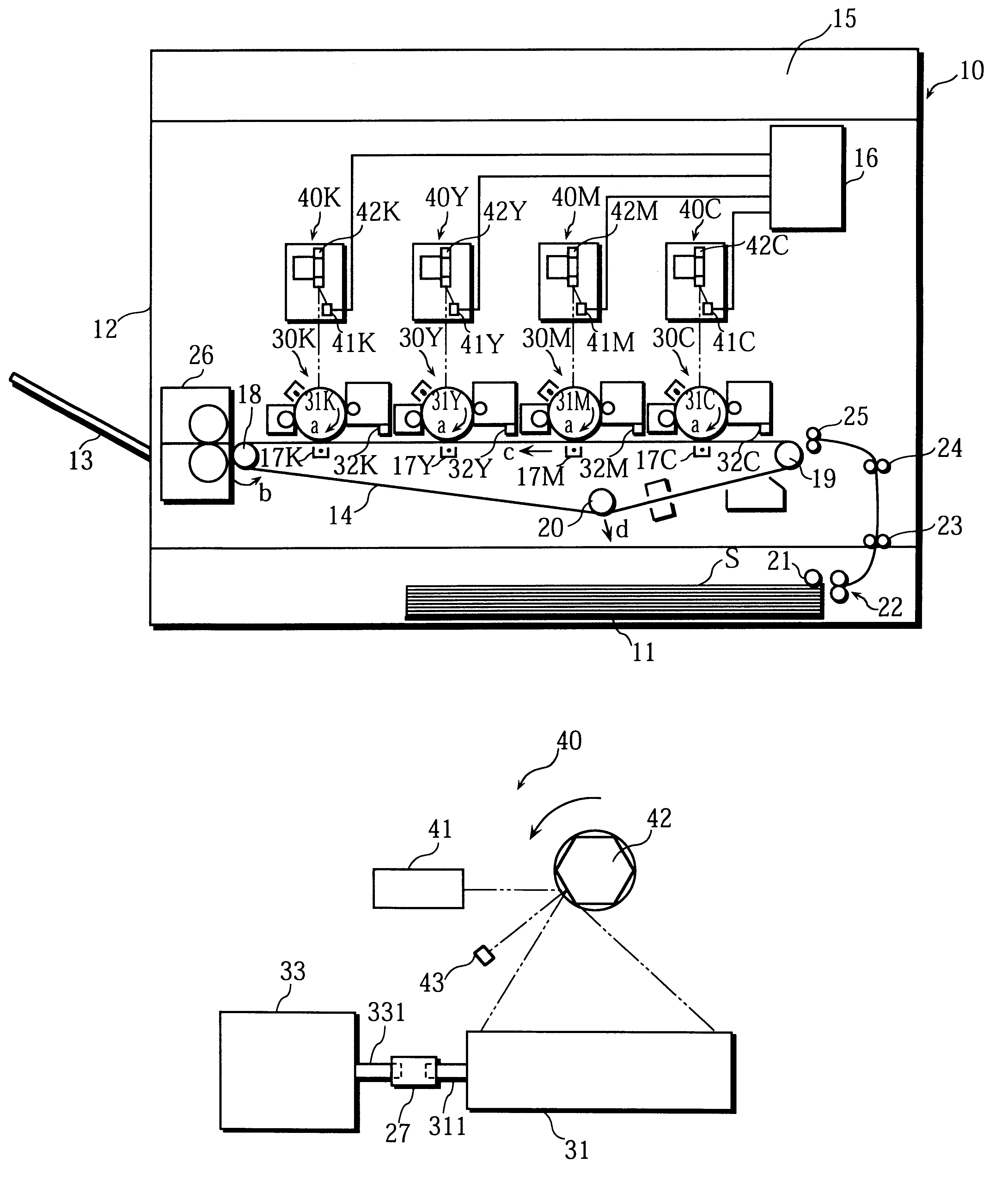
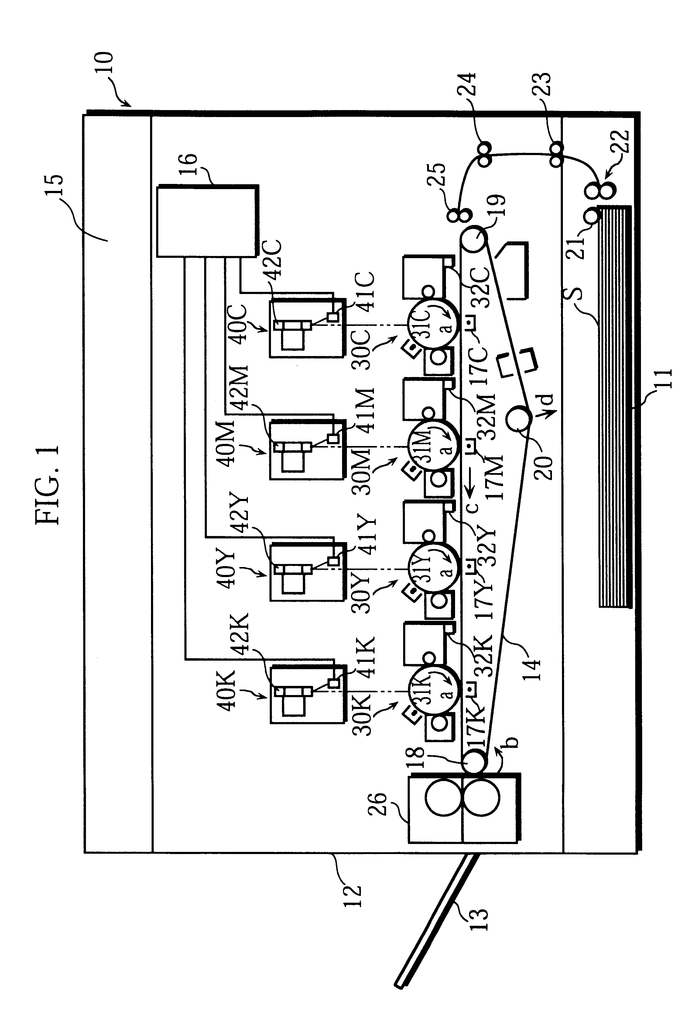
The following is a description of an embodiment of the image forming apparatus of the present invention. In the embodiment, a digital color copying machine (referred to as the "copier" hereinafter) is used as an example of such image forming apparatus.

FIG. 1 shows a front view of the copier. This copier is a so-called "tandem-type" copier. A paper feeding cassette 11 is set at the lowermost part of an enclosure 10 and can be freely slid in and out of the copier. A paper discharge tray 13 is set on a left-side wall 12 and protrudes outward. A transport belt 14 is horizontally set in a lower space above the paper feeding cassette 11. A plurality (four in FIG. 1) of image forming units 30C, 30M, 30Y, and 30K are set above the transport belt 14 along its length. The transport belt 14 transports a recording sheet S, and the image forming units 30C to 30K sequentially transfer toner images for respective colors onto the recording sheet S, the toner images being superimposed on the recordi...


PUM


Abstract

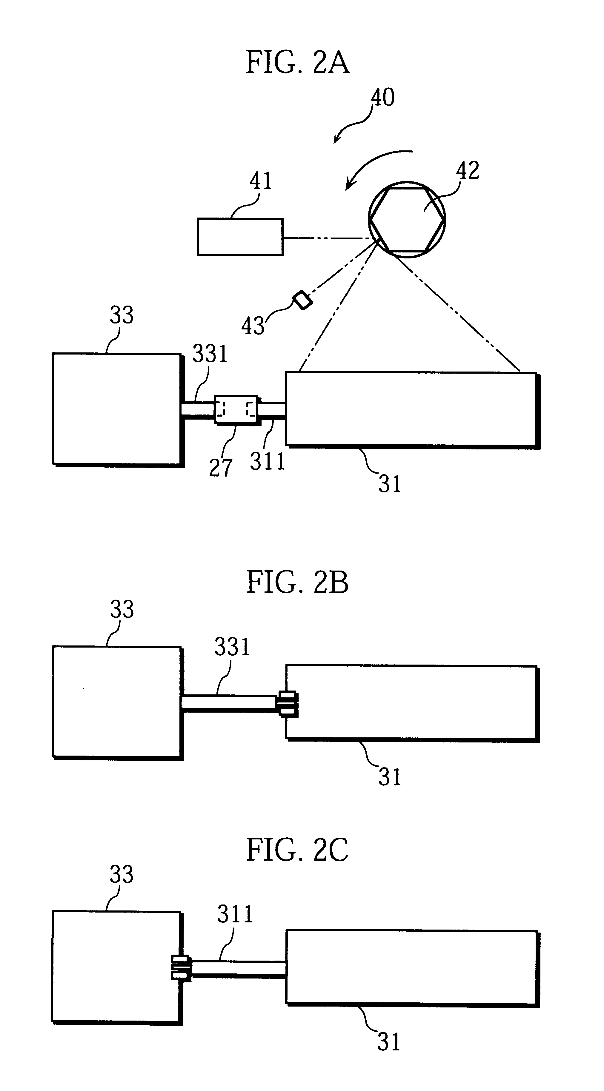
A rotational shaft of a photosensitive drum is connected to a rotational shaft of a stepping motor by a coupling, so that the stepping motor directly drives the photosensitive drum. Here, theta (°) indicating a step angle of the stepping motor, p (mm) indicating a distance between scanning lines on the photosensitive drum, pi indicating the circular constant, and d (mm) indicating a diameter of the photosensitive drum are set so as to satisfy an equation n.theta=(360.p) / (pi.d) to make an optical unit scan the photosensitive drum by one scanning line every time the photosensitive drum is made to rotate n steps, n being a positive integer.

Description

This application is based on an application No. 9-303901 filed in Japan, the content of which is hereby incorporated by reference.(1) Field of the InventionThe present invention relates to an image forming apparatus, and especially relates to an image forming apparatus provided with a photosensitive drum which is driven by a stepping motor.(2) Related ArtIn an electrophotographic type image forming apparatus, a toner image is formed on a photosensitive drum and the toner image is transferred onto a recording sheet to form an image. To transfer the toner image formed on the photosensitive drum onto the recording sheet with fidelity, a circumferential speed of the photosensitive drum needs to be precisely equal to a transportation speed of the recording sheet. For this reason, in recent years, a stepping motor is used as a driving source of the photosensitive drum for its high performance in braking in comparison with other kinds of motors.As one example of conventional image forming ...

Claims


Application Information

Patent Timeline
IPC IPC(8): B41J11/42B41J2/435B41J2/47H04N1/047H04N1/113H04N1/12G03G21/14G03G21/00
CPCB41J2/473B41J11/42H04N1/0473H04N1/1135H04N1/12H04N2201/0471H04N2201/04755H04N2201/04732H04N2201/04744H04N2201/02439H04N2201/04794
Inventor FUJIKURA, TERUHIKOHIGASHI, TOSHIKAZUTAMURA, TOMONOBUTAKASU, AKIRA
Owner MINOLTA CO LTD
Learn More