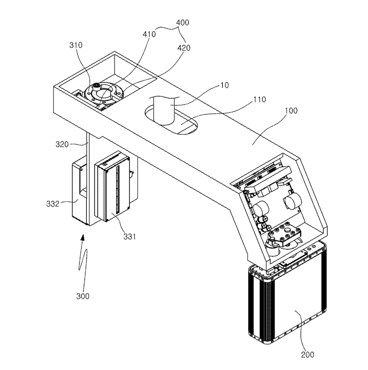
X-ray imaging apparatus

a technology of x-ray imaging and apparatus, applied in the field of x-ray imaging apparatus, to achieve the effect of simple structure, reduced production cost and simple structur

Active Publication Date: 2017-07-06
OSSTEMIMPLANT CO LTD
View PDF3 Cites 13 Cited by
  • Summary
  • Abstract
  • Description
  • Claims
  • Application Information

AI Technical Summary

Benefits of technology

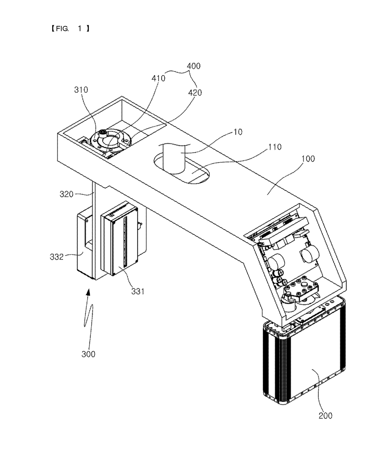
[0020]The present invention as described above may perform both the CT imaging and the panorama imaging and also realize the rotation of the sensor unit and the sliding movement of the rotation unit by using the only one driving part to embody the simple structure and reduce production costs.
[0021]Also, as the result of realizing the rotation of the sensor unit and the sliding movement of the rotation unit by using the only one driving part, the distance between the X-ray source unit and the sensor unit may be uniformly maintained. On the other hand, the distance between the X-ray source unit and the examinee may be changed so that the two imaging processes are enabled by adequately adjusting the magnification for the panorama image photographing or the CT imaging.
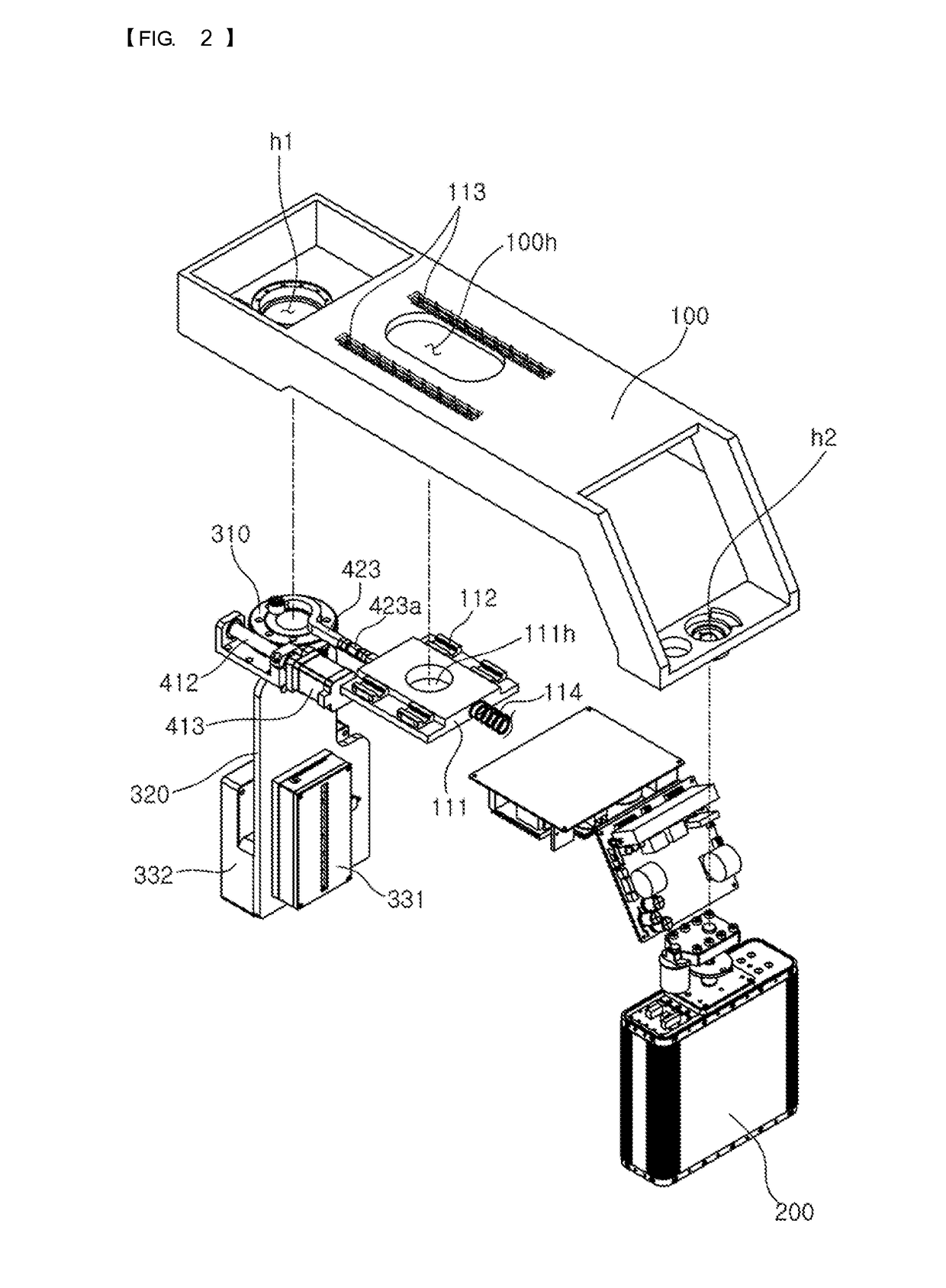
[0022]Also, the rotation of the sensor unit and the sliding movement of the rotation unit are interlocked with each other to achieve the simple structure through the simple link structure in which the pair of protruding pins are connected to the interlocking link.
[0023]Also, the length adjusting part may be disposed at the central portion of the interlocking link to finely adjust the interlock of the rotation of the sensor unit and the sliding movement of the rotation unit.
[0024]Also, the fixed plate may be prevented from being spaced from the rotation unit through the elastic part that elastically pulls the fixed plate to the source unit.

Problems solved by technology

However, the X-ray imaging apparatus for the CT may acquire only the tomographic image.

Method used


Image

  • X-ray imaging apparatus
  • X-ray imaging apparatus
  • X-ray imaging apparatus

Examples


Embodiment Construction

[0030]The present invention may be realized in other various forms without departing from the technical idea or the essential feature. Thus, the embodiments of the present invention may be merely illustrative in all aspects and should not be construed as limited thereto.

[0031]Although the terms such as first and second are used herein to describe various elements, these elements should not be limited by these terms.

[0032]The terms are only used to distinguish one element from other elements. For example, a first element can be referred to as a second element, and similarly a second element can be referred to as a first element without departing from the scope of the present invention.

[0033]The term ‘and / or’ includes a combination of a plurality of items relevantly described or any one of a plurality of items relevantly described.

[0034]It will also be understood that when an element is referred to as being “'connected to” or “engaged with” another element, it can be directly connecte...


PUM


Abstract

An X-ray imaging apparatus of the present invention includes: a rotation unit disposed on a lower end of a rotation shaft through a sliding part so as to enable a sliding movement along an irradiation direction of X-ray; an X-ray source unit disposed on a lower end of one side of the rotation unit; a sensor unit installed by disposing a shaft rotation part on a lower end of the other side of the rotation unit; a driving unit including: a driving part which provides drive power to the shaft rotation part; and an interlocking part configured to allow the rotation unit to slidably move to one side or the other side according to the rotation state of the shaft rotation part.

Description

TECHNICAL FIELD[0001]The present invention relates to an X-ray imaging apparatus, and more particularly, to an X-ray imaging apparatus which can perform both CT imaging and panorama imaging and also implement a rotation of a sensor unit and a sliding movement of a rotation unit with only one driving part, thereby having a simple structure and reducing production costs.BACKGROUND ART[0002]In general, in dental clinics, X-ray imaging apparatuses are installed to perform X-ray imaging so as to grasp a state of teeth and alveolar bones for the purpose of treating teeth and various types of periodontal disease or performing an orthodontic treatment of teeth set.[0003]In the X-ray imaging apparatuses used in the dental clinics, a predetermined amount of X-rays is transmitted to teeth that are body parts to be imaged, and the intensity of the transmitted X-rays is detected. The transmitted X-rays are converted into an electrical signal corresponding to the intensity of the X-rays and then ...

Claims


Application Information

Patent Timeline
Patent Type & Authority Applications(United States)
IPC IPC(8): A61B6/03A61B6/14A61B6/00A61B5/00
CPCA61B6/032A61B5/0035A61B6/02A61B6/4417A61B6/5247A61B6/14A61B6/035A61B6/4435A61B6/4452A61B6/588A61B6/589A61B6/4476A61B6/587
Inventor PARK, MOO-YONGWOO, JAE-HEE
Owner OSSTEMIMPLANT CO LTD
Why Eureka
Try Eureka