Water treatment device

Inactive Publication Date: 2008-11-20
SANYO ELECTRIC CO LTD
View PDF7 Cites 12 Cited by
  • Summary
  • Abstract
  • Description
  • Claims
  • Application Information

AI Technical Summary

Benefits of technology

[0007]The present invention has been developed to solve such a conventional technical problem, and an object thereof is to provide a water treatment device which improves the tre

Problems solved by technology

However, in the above water treatment device, the microorganisms can be adsorbed and removed, but the density of the current applied to the electrode is low.
Therefore, the microorganisms cannot be destroyed using electric shock or hypochlorous acid, and the conductor periodically needs to be taken out to remove the microorganism adsorbed by the conductor with the reagent or the like, so that maintenance and management are laborious.
Thus, there has been a

Method used


Image

  • Water treatment device
  • Water treatment device
  • Water treatment device

Examples


embodiment 1

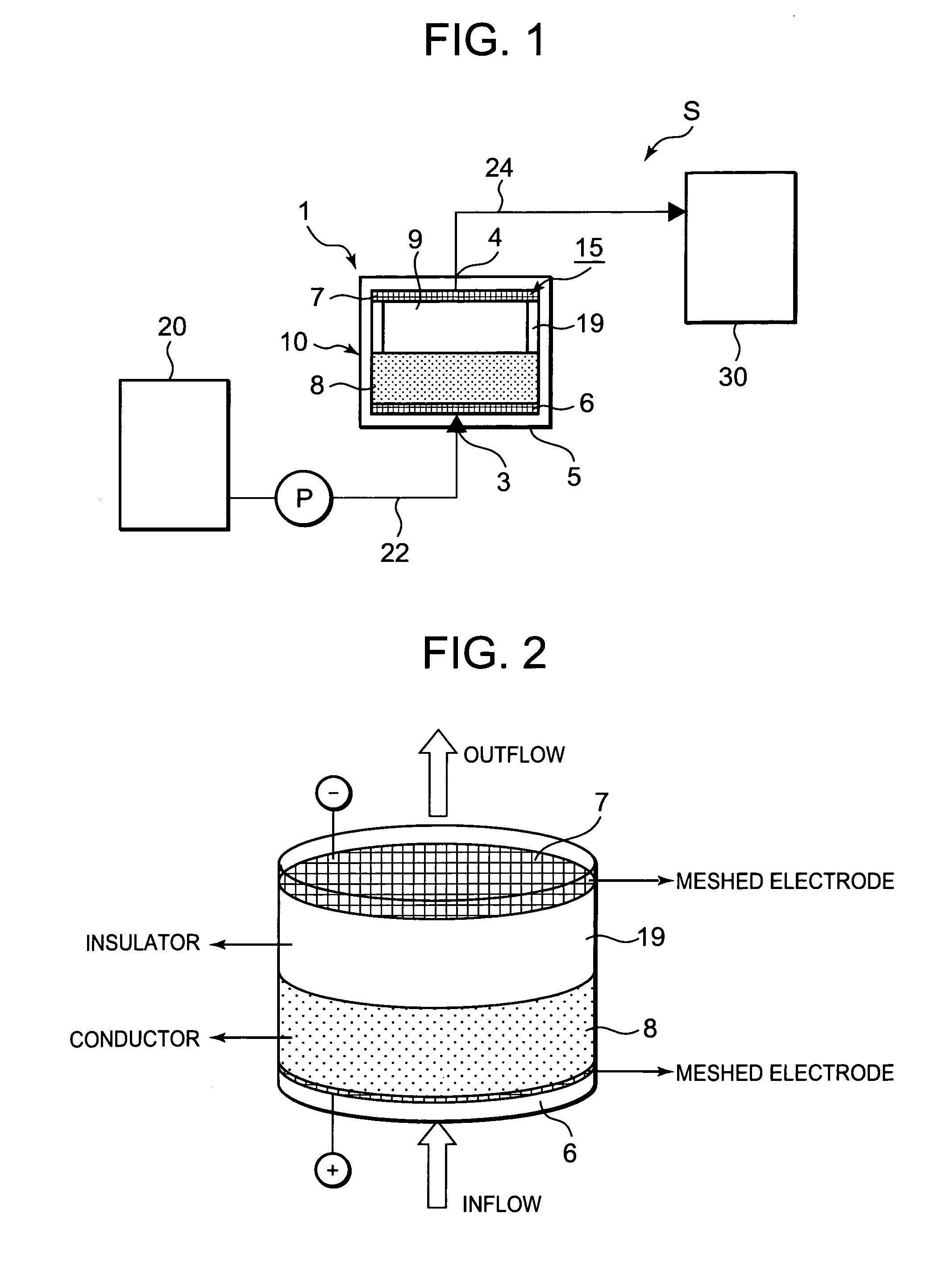
[0033]FIG. 1 is a schematic diagram showing a system S including a water treatment device according to one embodiment to which the present invention has been applied. The system S of the present embodiment is a water treatment system in which water (for-treatment water) such as rain water, ground water, water for beverage use, bath water or hot spring water received in a raw solution tank 20 is treated by a water treatment device 1 according to the present invention, and then received in a treated solution tank 30. The system is applied to, for example, a beverage manufacturing device or the like which treats the for-treatment water to form the water for beverage use. Then, the water treatment device 1 of the present invention is installed along the channel of the for-treatment water flowing from the raw solution tank 20 to the treated solution tank 30.

[0034]That is, the system S of the present embodiment is constituted by successively connecting the raw solution tank 20, the water ...

embodiment 2

[0093]It is to be noted that in Embodiment 1 described above, the water treatment device 1 to which the present invention is applied is disposed in the system S shown in FIG. 1 in which the for-treatment water received in the raw solution tank 20 is treated and received in the treated solution tank 30, but the present invention is not limited to this embodiment. The water treatment device 1 may be used in another system. Here, in the present embodiment, another embodiment will be described in a case where the water treatment device 1 to which the present invention is applied is disposed in the other system.

[0094]FIG. 11 is a diagram schematically showing the system of the other embodiment provided with the water treatment device 1 to which the present invention is applied. This system is an apparatus for removing or decomposing microorganisms and fine matters included in for-treatment water such as water (hot water) for use in public bath or hot spring. It is to be noted that in FIG...


PUM

PropertyMeasurementUnit
Fractionaaaaaaaaaa
Forceaaaaaaaaaa
Electrical conductoraaaaaaaaaa

Abstract

There is disclosed a water treatment device capable of improving the treatment efficiency of for-treatment water and passing the for-treatment water once to sufficiently treat the water without repeatedly circulating the water, and the water treatment device includes a water passing first electrode arranged in the channel of the for-treatment water, a conductive fiber positioned on the downstream side of this first electrode and energized by the first electrode, a water passing second electrode positioned on the downstream side of this conductive fiber and forming a pair with the first electrode, an insulating porous spacer interposed between this second electrode and the conductive fiber, and a supply section which supplies voltages to both of the electrodes.

Description

BACKGROUND OF THE INVENTION[0001]The present invention relates to a germ removal or sterilization treatment of microorganisms such as viruses included in rivers, water for beverage use or water (such water to be treated will hereinafter be referred to as the for-treatment water) for use in a pool, public bath, hot spring or the like, and it also relates to a water treatment device for removing a scale.[0002]In recent years, a water treatment technology for removing microorganisms such as bacteria, mold and protozoa included in rivers, water for beverage use, or water (for-treatment water) for use in public bath, hot spring or the like has rapidly developed.[0003]As one of such water treatment devices, the applicant has previously developed a device including a pair of electrodes and a conductor capable of trapping the microorganisms in the channel of the for-treatment water, whereby a positive charge is applied to this conductor, and a negative charge is applied to the electrodes, t...

Claims


Application Information

Patent Timeline
IPC IPC(8): C02F1/461
CPCC02F1/288C02F1/4602C02F1/469C02F1/48C02F2001/46157C02F2303/04C02F2303/22
Inventor OGAWA, YUIOE, HANAUMEZAWA, HIROYUKI
Owner SANYO ELECTRIC CO LTD
Why Eureka
Try Eureka