Variable color print with locally colored regions and method of making same

a technology of color printing and local color, applied in the field of variable color printing with, can solve the problems of high cost, high process cost, and high cost of manufacturing diffraction grating

Inactive Publication Date: 2001-01-23
MANCUSO ROBERT J
View PDF7 Cites 37 Cited by
  • Summary
  • Abstract
  • Description
  • Claims
  • Application Information

AI Technical Summary

Benefits of technology

It is therefore an object of this invention to provide an improved multi-colored variable color print which

Problems solved by technology

The process of manufacturing the diffraction grating requires great accuracy and is very expensive.
Ho

Method used


Image

  • Variable color print with locally colored regions and method of making same
  • Variable color print with locally colored regions and method of making same
  • Variable color print with locally colored regions and method of making same

Examples


Embodiment Construction

Other objects, features and advantages will occur to those skilled in the art from the following description of a preferred embodiment and the accompanying drawings, in which:

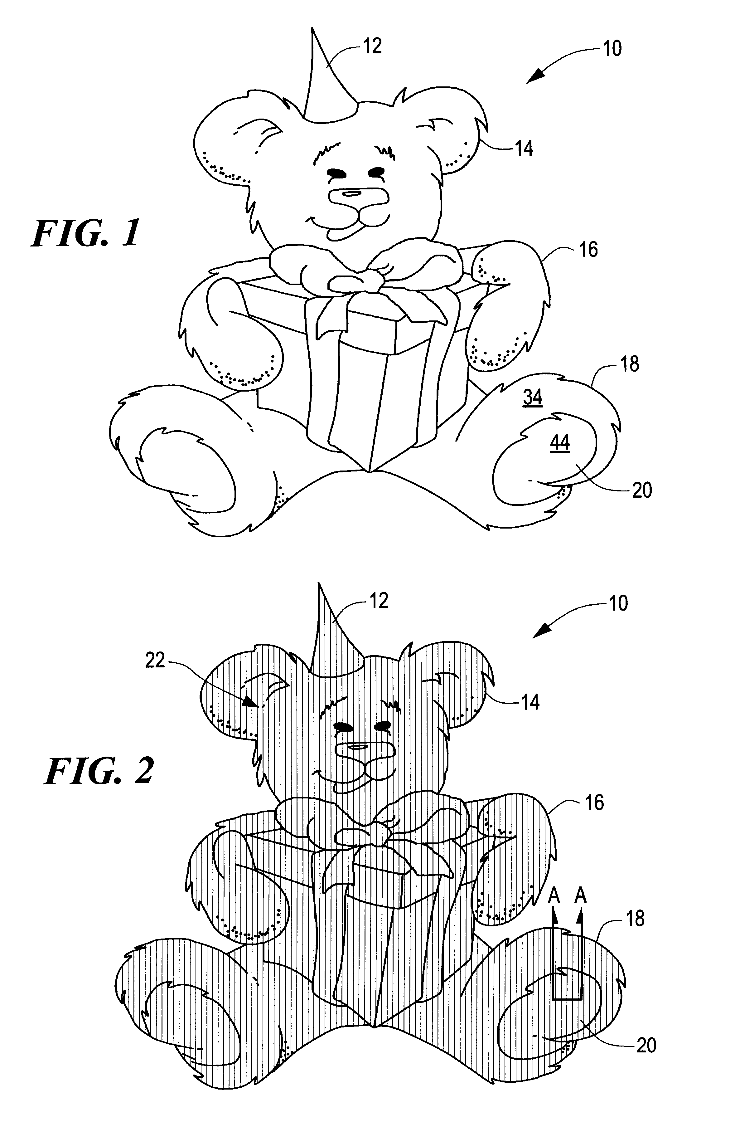
FIG. 1 is schematic top plan view of a variable color print according to this invention generated by several adjacent and differently colored local regions;

FIG. 2 is a schematic top plan view of the variable color print of FIG. 1 showing the orientation of lines which are representative of the periodic optical variations of the image medium in adjacent local regions;

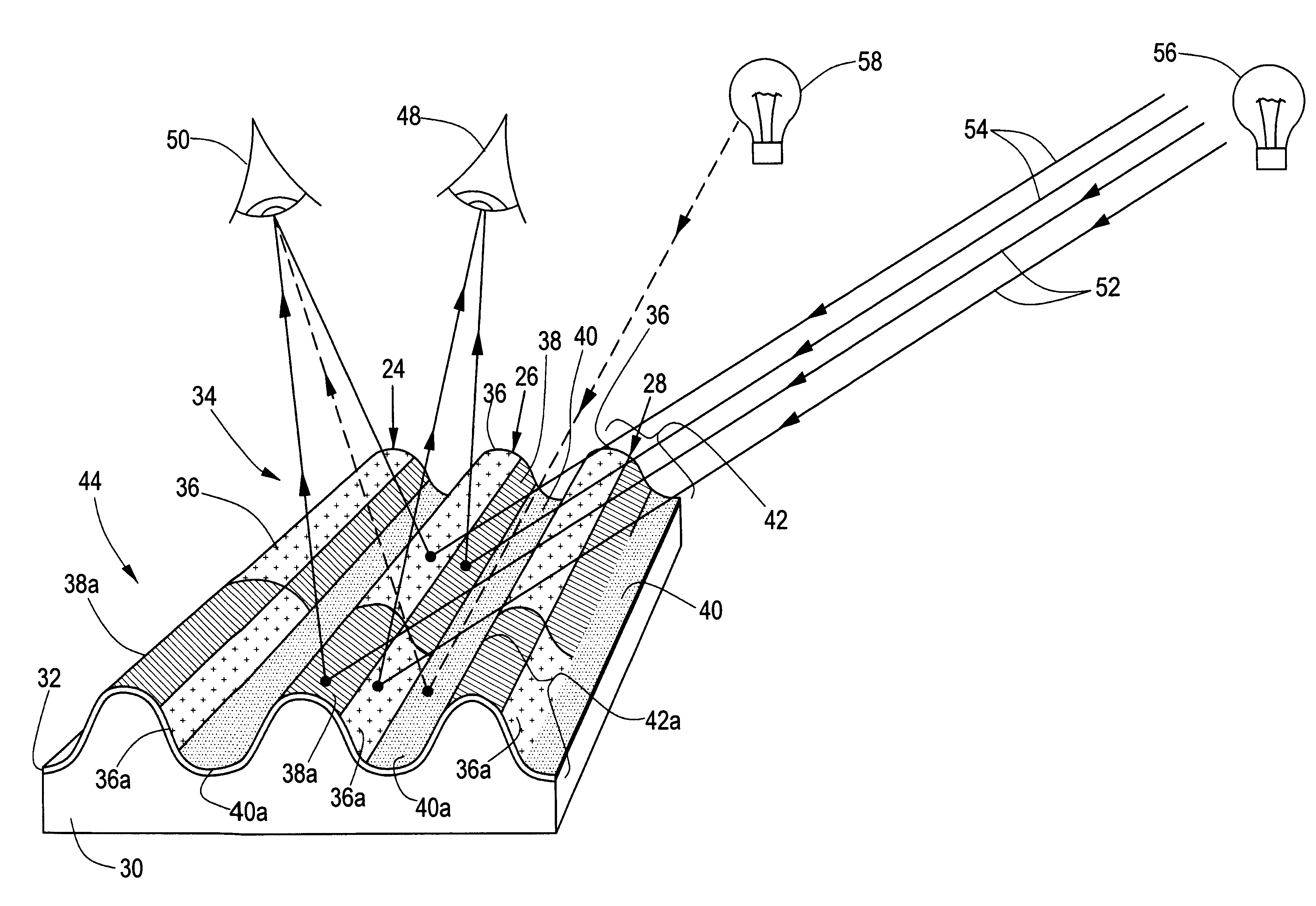
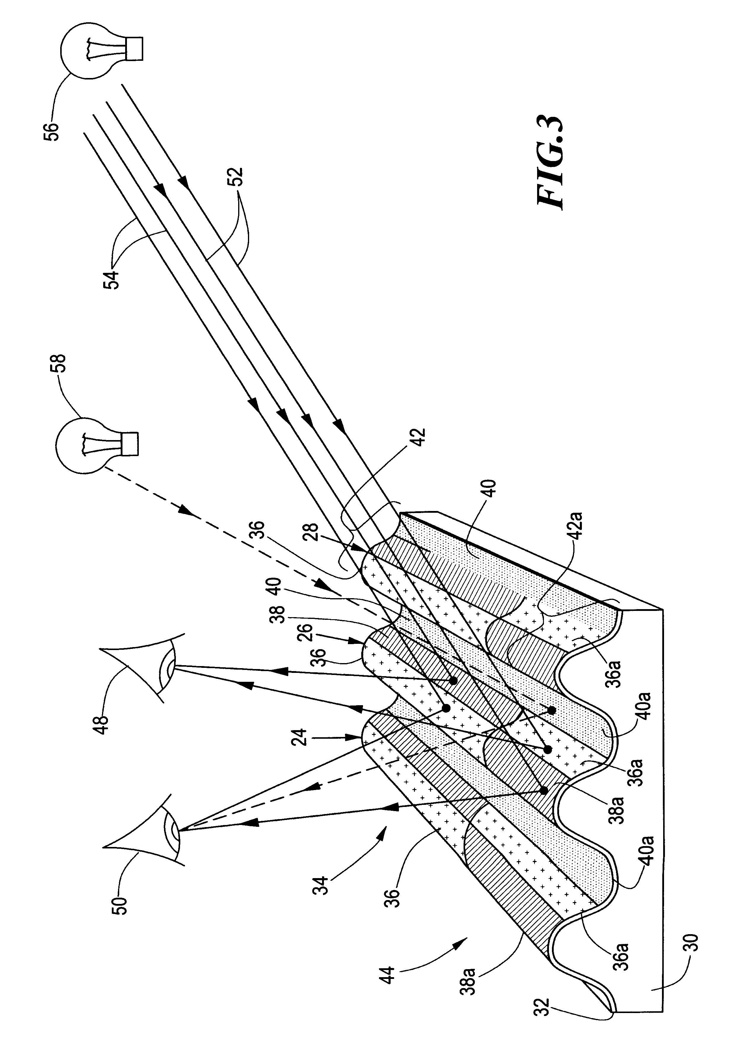
FIG. 3 is a greatly enlarged schematic axonometric view along a portion of line A--A of FIG. 2 showing embossed grooves and aligned colors assigned to adjacent local color regions which are selectively subdued and revealed at different viewing angles;

FIG. 3A is greatly enlarged schematic, similar to FIG. 3, in which one color variation runs parallel with the embossing and one color variation runs transverse to the embossing.

FIG. 4 is a greatly enlar...


PUM


Abstract

A variable color print of an image includes a reflective image medium including a plurality of different, locally colored, image regions; a first plurality of repeated changes in reflective angle of the image medium which extend in a first direction and are parallel to each other in a second direction transverse to the first direction; each locally colored image region including at least one local color medium disposed on the reflective medium; each local color medium includes at least one color sequence, each sequence extending in the second direction and including at least two different color variations; and each color variation is aligned with the repeated changes in reflective angle such that the repeated changes in reflective angle selectively prevent viewing of at least one of the color variations and selectively highlight at least one of the color variations at different viewing angles to generate changes in color of the locally colored image regions as the viewing angle changes.

Description

This invention relates to a color print and method of making same, and more particularly to such a print including a number of different local colored regions having optical variations which selectively permit viewing of one or more local colors at different viewing angles.BACKGROUND OF INVENTIONA number of different objects display different images, or different views of an image, depending on the angle by which the object is viewed. Some objects, such as holographs, utilize diffraction to separate white light into in its spectral components. A diffraction grating, having 20,000 to 50,000 lines per inch, reflects or transmits different portions of the incident spectrum. The portions are seen as a view of an image which changes as the angle of incidence changes. The process of manufacturing the diffraction grating requires great accuracy and is very expensive.Rather than utilize the diffraction principal, some objects are provided with embossed foil having far fewer lines per inch w...

Claims


Application Information

Patent Timeline
IPC IPC(8): B42D15/00
CPCB42D15/00B42D2035/24B41M1/14
Inventor MANCUSO, ROBERT J.
Owner MANCUSO ROBERT J
Why Eureka
Try Eureka