Eureka AIR delivers breakthrough ideas for toughest innovation challenges, trusted by R&D personnel around the world.

Resonant EAS marker with sideband generator

Inactive Publication Date: 2001-01-23
SENCORMATIC ELETRONICS LLC
View PDF10 Cites 78 Cited by
  • Summary
  • Abstract
  • Description
  • Claims
  • Application Information

AI Technical Summary

Benefits of technology

According to a preferred embodiment of the invention, the magnetic element included in the coil exhibits a giant magneto-impedance (GMI) effect when a bias magnetic field is applied to the magnetic element. A marker of this type may be interrogated by simultaneously transmitting a carrier signal at the marker's resonant fre

Problems solved by technology

When the fusible link is energized and caused to fuse, an open circuit is formed in the resonant circuit of the marker, causing the marker to be detuned and no longer detectable by the detection portion of the EAS system.
Furthermore, known techniques for deactivating resonant circuit markers are irreversible, in that once a fusible link is fused or the capacitor is broken down, the marker cannot be reactivated.

Method used


Image

  • Resonant EAS marker with sideband generator
  • Resonant EAS marker with sideband generator
  • Resonant EAS marker with sideband generator

Examples


Embodiment Construction

Preferred embodiments of the invention will now be described, with reference to the drawings.

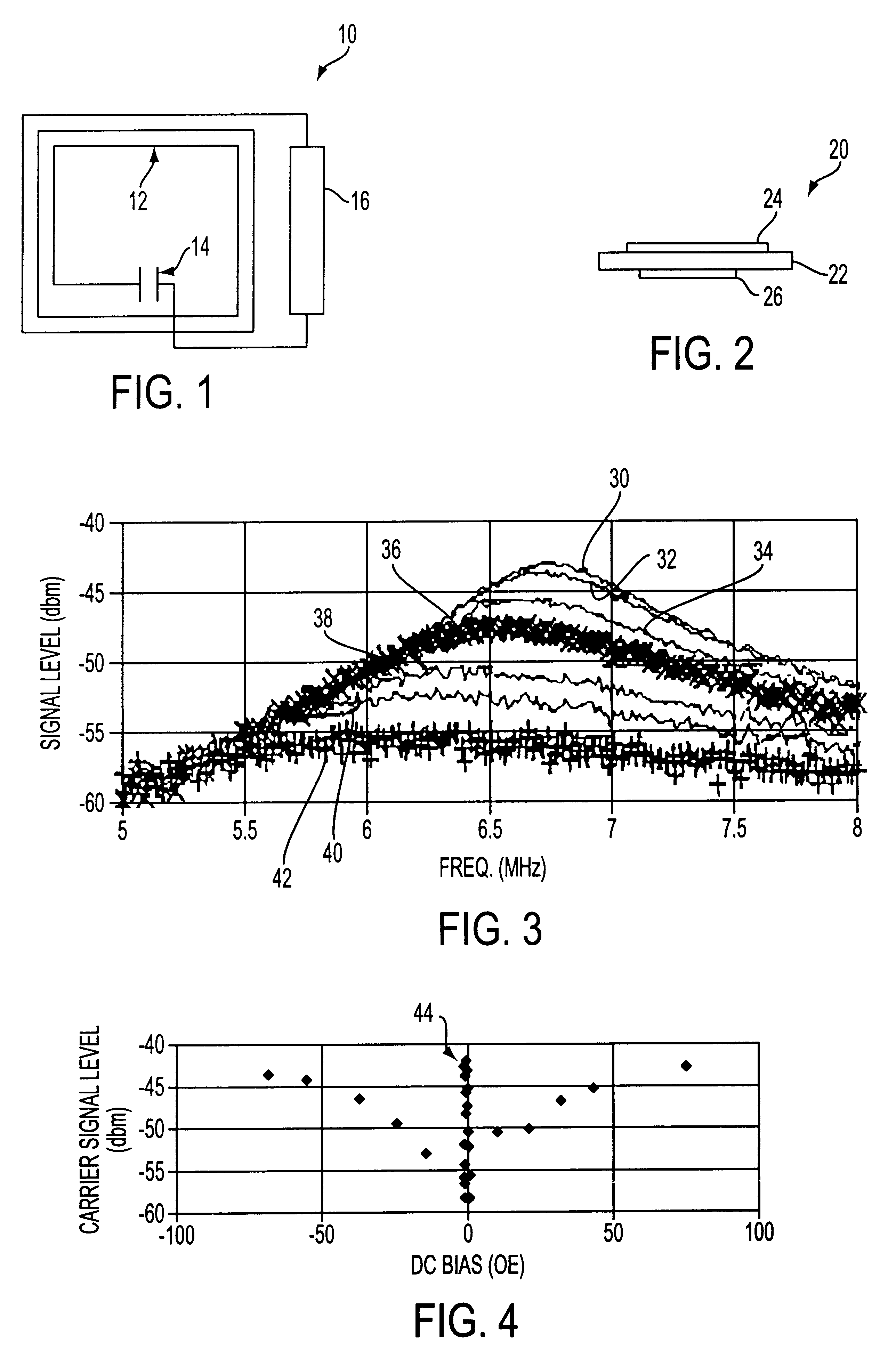
Referring initially to FIG. 1, reference numeral 10 generally indicates a resonant circuit provided, in accordance with the invention, as the active component of an EAS marker. The circuit 10 includes a coil indicated at 12 and a capacitor connected to the coil and indicated at 14. One leg of the coil 12 is constituted by a magnetic element 16. The magnetic element is of a type which exhibits a so-called "giant magneto-impedance" (GMI) effect. GMI effects have been extensively studied in recent years and are said to occur when a voltage induced by a high frequency current source in a ferromagnetic wire is caused to change substantially by applying an external magnetic field to the wire. The magnetic element 16 may take the form of a 6 cm length of amorphous cobalt-based wire, having a diameter of 116 microns. The amorphous cobalt-alloy wire may be formed by a conventional technique such as c...


PUM


Abstract

A resonant RF electronic article surveillance marker includes a substrate, a coil formed on the substrate, and a capacitor formed on the substrate. The coil includes a magnetic element which exhibits a GMI effect. Two signals are employed to interrogate the marker-an RF carrier signal and a low-frequency alternating magnetic field. Because of the presence of the GMI element, the marker mixes the low frequency signal with the carrier signal to generate a sideband of the carrier signal. The sideband signal is very unique and can be detected with a high degree of reliability. The marker may also include magnetic control elements which can be magnetized to disable the marker and de-magnetized to reactivate the marker.

Description

This invention relates to electronic article surveillance (EAS) systems.It is well known to provide electronic article surveillance systems to prevent or deter theft of merchandise from retail establishments. In a typical system, markers designed to interact with an electromagnetic field placed at the store exit are secured to articles of merchandise. If a marker is brought into the field or "interrogation zone", the presence of the marker is detected and an alarm is generated. Some markers are intended to be removed at the checkout counter upon payment for the merchandise. Other types of markers remain attached to the merchandise but are deactivated upon checkout by a deactivation device which changes a characteristic of the marker so that the marker will no longer be detectable at the interrogation zone.A known type of EAS system employs markers which include an LC resonant circuit. An example of such a system is disclosed in U.S. Pat. No. 3,810,147. The circuit is typically forme...

Claims


Application Information

Patent Timeline
IPC IPC(8): G08B13/24
CPCG08B13/2411G08B13/2414G08B13/2431G08B13/2448
Inventor LIAN, MING-RENPATTERSON, HUBERT A.
Owner SENCORMATIC ELETRONICS LLC
Why Eureka
Eureka Blog
Learn More