Apparatus and method for testing optical fiber system components

a technology of optical fiber and system components, applied in the field of switches, can solve the problems of inefficient and/or insufficiently and/or adequately automated testing system, inability to test all desired properties of fiber optic devices, complex testing procedure,

Inactive Publication Date: 2001-01-23
BLOOM CARY
View PDF91 Cites 96 Cited by
  • Summary
  • Abstract
  • Description
  • Claims
  • Application Information

AI Technical Summary

Problems solved by technology

Thus, in the Longhurst reference, the testing procedure is complex and cumbersome.
Further, all desired properties of the fiber optic device cannot be tested without additional connections being made, and/or operations being conducted and/or additional testing equipment being required, between different test procedures.
Thus, the testing system in the Longhurst reference is inefficient and not sufficiently and/or adequately automated.
However, I have realized that this switching assembly (suggested for use for environmental testing of fiber optic d

Method used


Image

  • Apparatus and method for testing optical fiber system components
  • Apparatus and method for testing optical fiber system components
  • Apparatus and method for testing optical fiber system components

Examples


Embodiment Construction

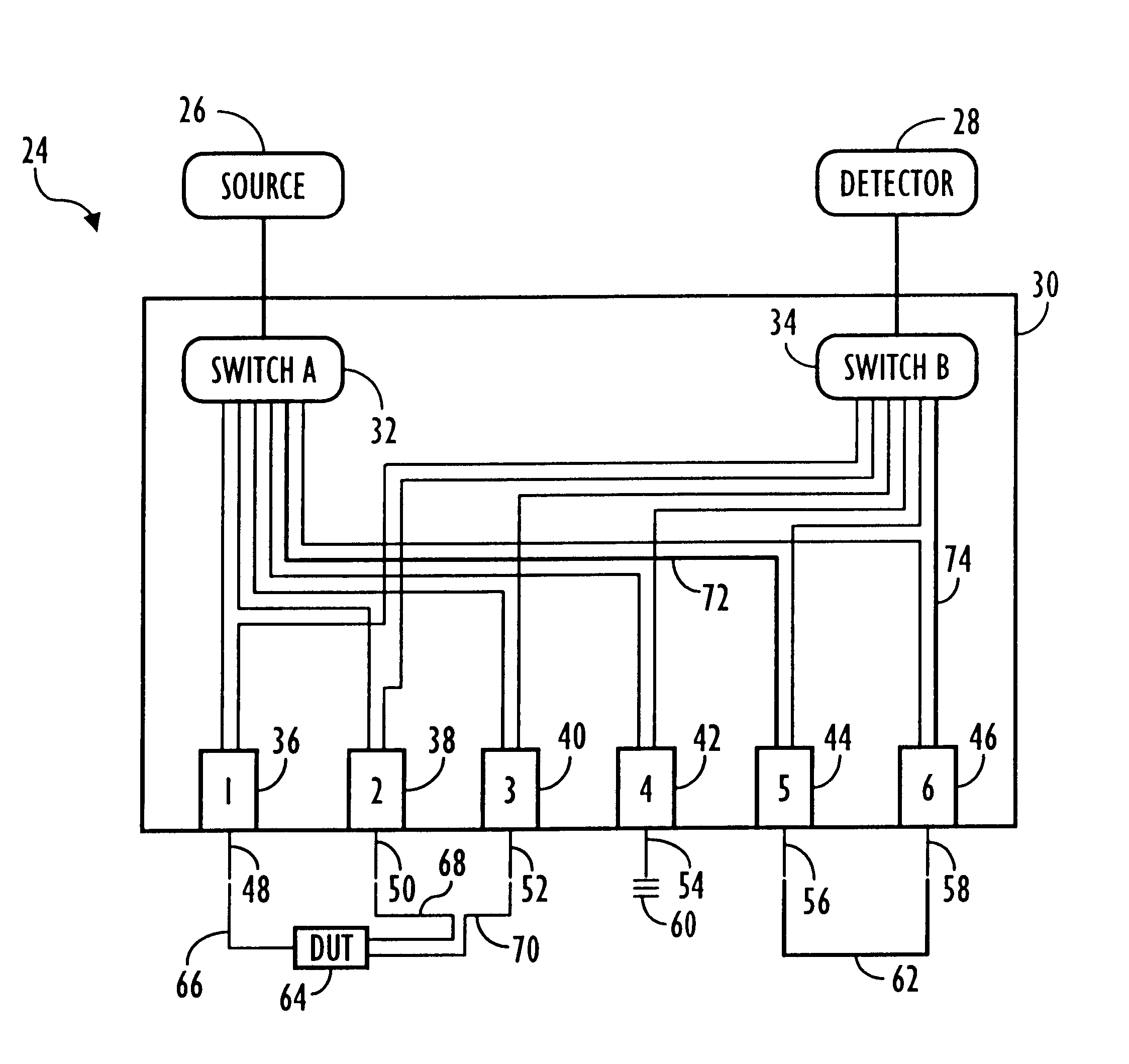
The present invention is used on, and provides efficient, accurate, rapid and reliable testing of, optical fibers, devices and / or fiber optic devices (hereinafter "fiber optic device") such as couplers, switches, wave-division multiplexers (WDM), filters, attenuators, polarizers, waveguides, sensors, wideband fiber optic couplers, fiber optic connectors, fiber optic amplifiers, fiber optic sensors and the like, that provide substantially similar optical responses, properties and / or indicators. These various fiber optic devices, such as the WDM, may be constructed of different materials such as glass, crystal, metal, plastic, ceramic and the like.

The present invention completely, accurately, and reliably tests a fiber optic device for all relevant optical characteristics. The present invention facilitates and / or performs the testing of optical characteristics of fiber optic devices such as couplers, switches, WDMs, and the like, to, for example, industry standard specifications, such...


PUM


Abstract

An optical switching assembly selectively connects an optical source and a detector to at least one fiber optic device. The assembly includes first and second groups of optical paths, and first and second optical switches. The first optical switch selectively connects the optical source to one end of the first group of optical paths, and the second optical switch selectively connects the detector to the one end of the second group of optical paths. The assembly laos includes a plurality of junctions, each having a lead associated therewith, and one or more of the leads are connected to the fiber optic device. The junctions connect the other end of the first group of optical paths and the other end of the second group of optical paths to the lead to facilitate the testing of the fiber optic device.

Description

1. Field of the InventionThe present invention relates to switching assemblies, and more specifically, to switching assemblies, and / or optical switches used for testing optical fibers, devices, and / or fiber optic devices, such as fiber optic couplers. The present completely, accurately, and reliably tests a fiber optic device for some, many and / or all relevant optical characteristics.2. Background of the Related ArtFiber optic devices are typically tested after manufacture to determine their optical characteristics. For example, attenuators may be tested to determine the actual attenuation of the device, and fiber optic couplers may be tested to determine the coupling ratio at selected wavelengths and polarizations.Currently, various techniques and / or switching assemblies are available for testing of fiber optic devices. For example, FIGS. 1A-1B illustrate one testing assembly disclosed in United Kingdom Patent Application 2235043A to Philip C. Longhurst, incorporated herein by refe...

Claims


Application Information

Patent Timeline
IPC IPC(8): G01M11/00G02B6/38G02B6/255G02B6/28G02B6/36G02B6/42
CPCG01M11/31G01M11/33G01M11/39G02B6/2551G02B6/2835G02B6/36G02B6/3837G02B6/3862G02B6/3887G02B6/3897G02B6/4248G01M11/00
Inventor BLOOM, CARY
Owner BLOOM CARY
Why Eureka
Try Eureka