Fluid pressure cylinder with a lock mechanism

a technology of locking mechanism and fluid pressure cylinder, which is applied in the direction of fluid-pressure actuators, etc., can solve the problem of difficult to provide space for the valve body

Inactive Publication Date: 2001-01-30
SMC CORP
View PDF10 Cites 49 Cited by
  • Summary
  • Abstract
  • Description
  • Claims
  • Application Information

AI Technical Summary

Benefits of technology

It is another object of the present invention to provide a fluid pressure cylinder with a lock mechanism which features good response and a stable braking force.
Since the release piston is provided on the side of the outer end of the lock mechanism cover, as is the pressure chamber that drives the release piston, a cylinder port through which compressed air is fed or discharged to drive the piston and a cushion valve for damping the piston can be disposed near the cylinder on the lock mechanism cover, and the unlocking port through which compressed air is supplied to unlock the piston rod and a manual opening actuator can be installed on the side of the outer end of said cover. This in turn means that the ports can be dispersed on the lock mechanism cover, so that a flat area in the viinity of the unlocking port can be provided for valves that control the cylinder and lock mechanism. This includes an area on the lock mechanism cover near the cylinder port for istalling the valves. As a result, a fluid pressure cylinder with a lock mechanism can be provided wherein it is advantageous if the cylinder is used separately, if it is necessary to determine which valve corresponds to which fluid pressure cylinder, or if the response of the lock mechanism needs to be increased.
In the lock mechanism, the brake shoes and shoe holder are provided inside the lock mechanism cover so that the shoes and holder can slide radially; the tapered ring and retainer are floated radially; many receiving pockets receiving the balls are provided in two rows around the retainer, the receiving pockets on the side of the release piston receiving balls of a large diameter and those on the opposite side receiving balls of a small diameter; and an elastic ring is wound in a V-shaped groove formed on one side of the outer circumference of the two rows of pockets around the retainer to prevent the balls from falling off and urge them in the direction tangential to the outer circumference of the shoe holder, so that a well-balanced, highly responsive, and stable braking force can be applied to the piston rod according to its eccentricity.
Such a fluid pressure cylinder with a lock mechanism according to the present invention makes it possible to ensure on the lock mechanism cover an area for installing valves to control the cylinder and lock mechanism. This configuration is advantageous if the cylinder is used separately, if it is necessary to determine which valve corresponds to which fluid pressure cylinder, or if the response of the lock mechanism needs to be increased. The present invention provides a fluid pressure cylinder featuring a highly responsive lock mechanism and a highly stable braking force.

Problems solved by technology

These requirements make it difficult to provide space where the valves can be installed on the rod-side cover of the cylinder with lock mechanism.

Method used


Image

  • Fluid pressure cylinder with a lock mechanism
  • Fluid pressure cylinder with a lock mechanism
  • Fluid pressure cylinder with a lock mechanism

Examples


Embodiment Construction

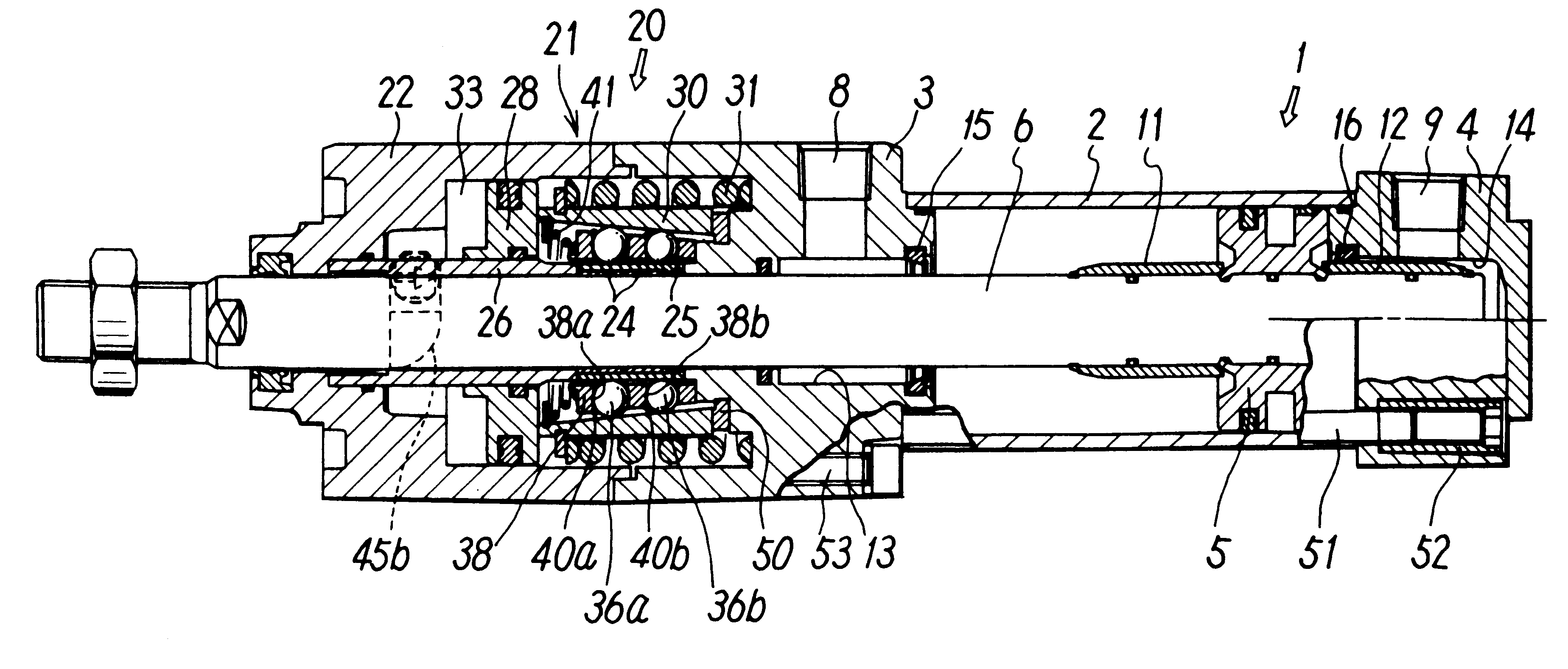
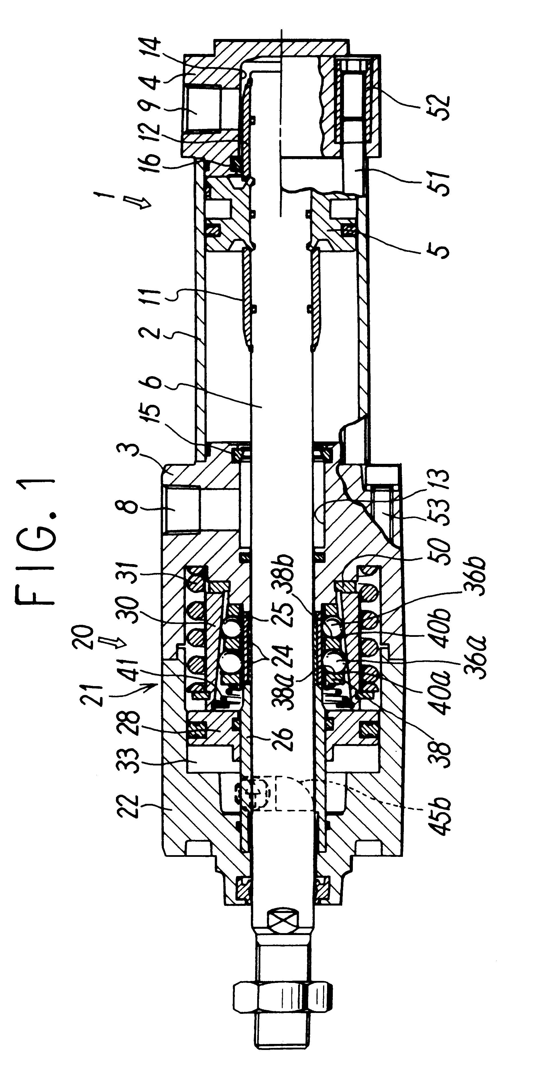
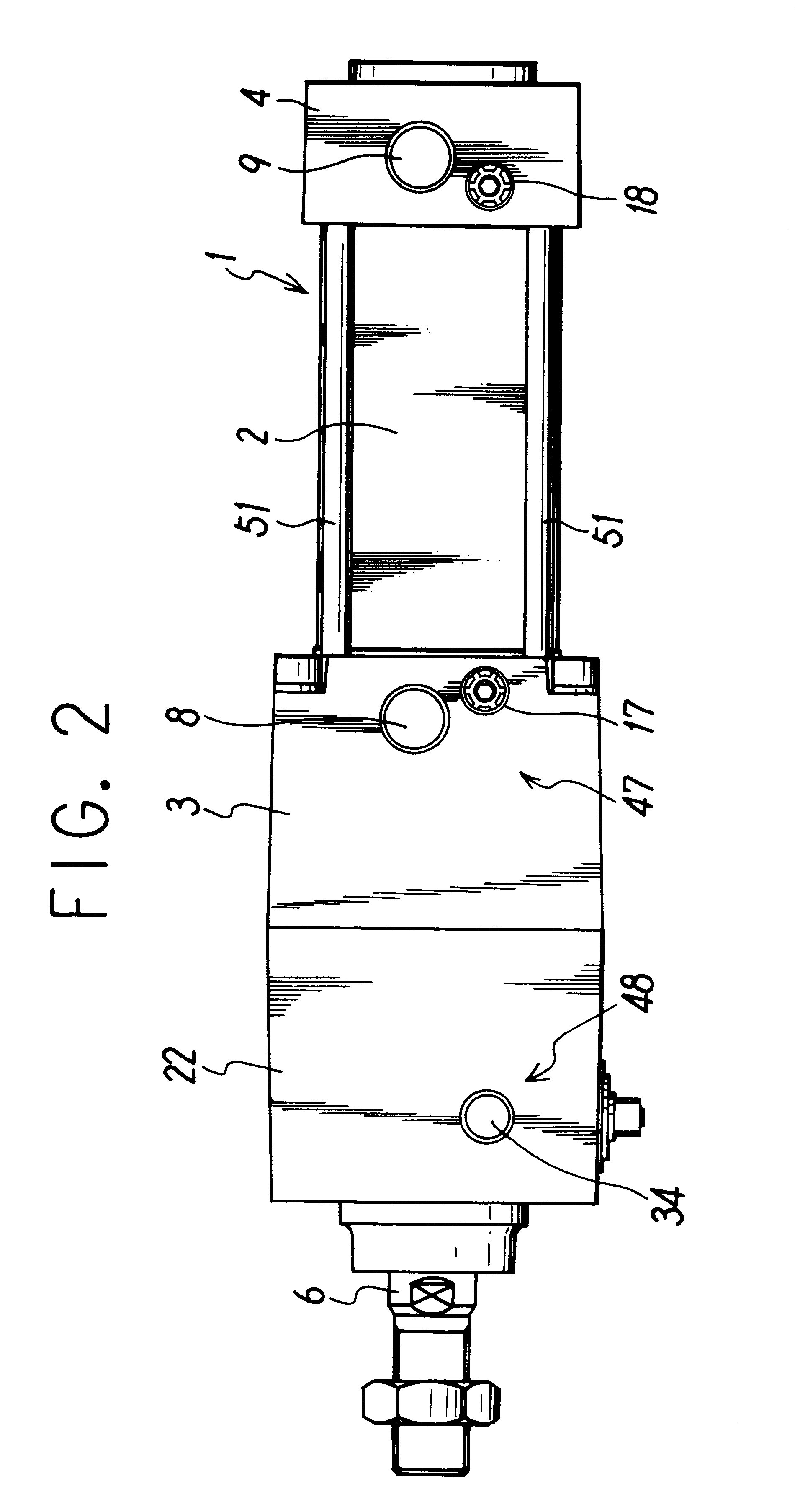
FIGS. 1 through 4 show an embodiment of a fluid pressure cylinder with a lock mechanism according to the present invention. The cylinder 1 has a cylinder tube 2, a rod cover 3, and a head cover 4, which are installed at both ends of the cylinder tube 2, a piston 5 that slides into the tube 2, and a piston rod 6 connected with the piston 5 and led out through the rod cover 3. The cylinder is intended to feed compressed air to pressure chambers on both sides of the piston 5 or discharge it from the chambers through cylinder ports 8 and 9, which are provided in the rod cover 3 and head cover 4 respectively.

The cylinder 1 also has a known air cushion mechanism which damps the piston 5. That is, cushion rings 11 and 12 are fitted over the piston rod 6 on both sides of the piston 5, and recesses 13 and 14 which the cushion rings 11 and 12 fit into together with the piston rod 6 at the end of a stroke are formed in the rod cover 3 and head cover 4 respectively. Cushion packings 15 and 16 w...


PUM


Abstract

This fluid pressure cylinder with a lock mechanism is adapted to provide, on the lock mechanism cover, an area where valves for controlling the cylinder and lock mechanism can be installed. In the cylinder, a brake shoe grips a piston rod 6 via balls held by a retainer inside a lock mechanism cover 21 using a tapered ring which is driven by a brake spring and returned to its original position by a release piston. A cylinder port 8 that supplies or discharges compressed air to drive the piston is provided on the side of a cylinder 1 inside the lock mechanism cover 21. On the opposite side an unlocking port 34 which leads to a pressure chamber driving a release piston is disposed and a manual opening actuator 45 is provided. This arrangement is intended to ensure a flat area 48 where valves can be installed to control compressed air fed through the ports.

Description

The present invention relates to a fluid pressure cylinder provided with a lock mechanism which grips a piston rod, thus keeping the rod at rest against fluid pressure.PRIOR ARTLock mechanisms have been incorporated in fluid pressure cylinders to stop the piston rod in a certain position. In such a mechanism, a brake shoe is pressed against the piston rod through balls, using a tapered ring whose internal surface is tapered. Using a brake spring, the lock mechanism urges the tapered ring in the direction of braking to lock the piston rod through the balls, thus holding the tapered ring in an unlocking position using a release piston that is driven by lock-release air pressure.Because a fluid pressure cylinder with such a lock mechanism is driven using air pressure and because its lock mechanism is also deactivated using air pressure, a plurality of air pressure pipe lines with valve control to supply air to the cylinder or discharge it from the cylinder must be connected to the cyli...

Claims


Application Information

Patent Timeline
Patent Type & Authority Patents(United States)
IPC IPC(8): F15B15/00F15B15/26
CPCF15B15/262F15B15/14
Inventor TAKAHASHI, HIDEHITO
Owner SMC CORP
Why Eureka
Try Eureka