Method and apparatus for installing a cable into coiled tubing

a technology of cable conductors and cable cables, applied in the direction of cables, cables, cables, etc., can solve the problems of cable conductors being inserted into tubing or conduits, increasing complexity and flexibility of the overall system, and difficulty in insertion

Inactive Publication Date: 2001-01-30
CAMCO INT
View PDF18 Cites 48 Cited by
  • Summary
  • Abstract
  • Description
  • Claims
  • Application Information

AI Technical Summary

Problems solved by technology

Certain systems of this type also include ancillary equipment such as fluid separators, injection pumps, and so forth, adding to the complexity and flexibility of the overall system.
A difficulty arises, however, in insertion of the cable conductors in the tubing or conduit.
Significant disadvantages have been encountered in tensioning techniques for deploying cables in conduit such as coiled tubing.
Such forces can result in damage to the cable during installation process.
Moreover, excessive tension in the cable can lead to stretching of the cable during installation.
During subsequent operation, the residual strain can be relieved, leading to contraction of the cable and, in certain cases, interruption of electrical power between the submerged equipment and wellhead equipment.

Method used


Image

  • Method and apparatus for installing a cable into coiled tubing
  • Method and apparatus for installing a cable into coiled tubing
  • Method and apparatus for installing a cable into coiled tubing

Examples


Embodiment Construction

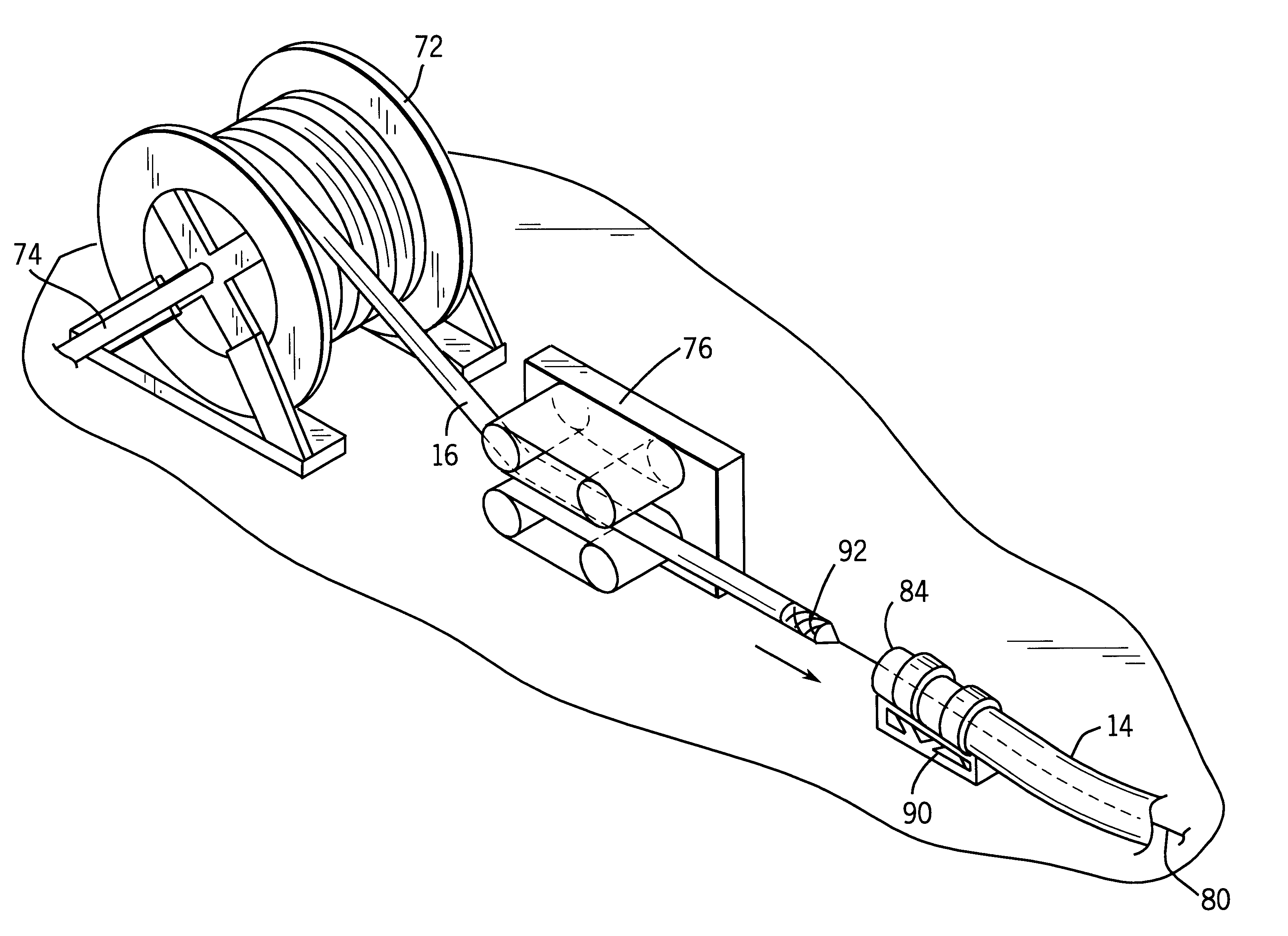
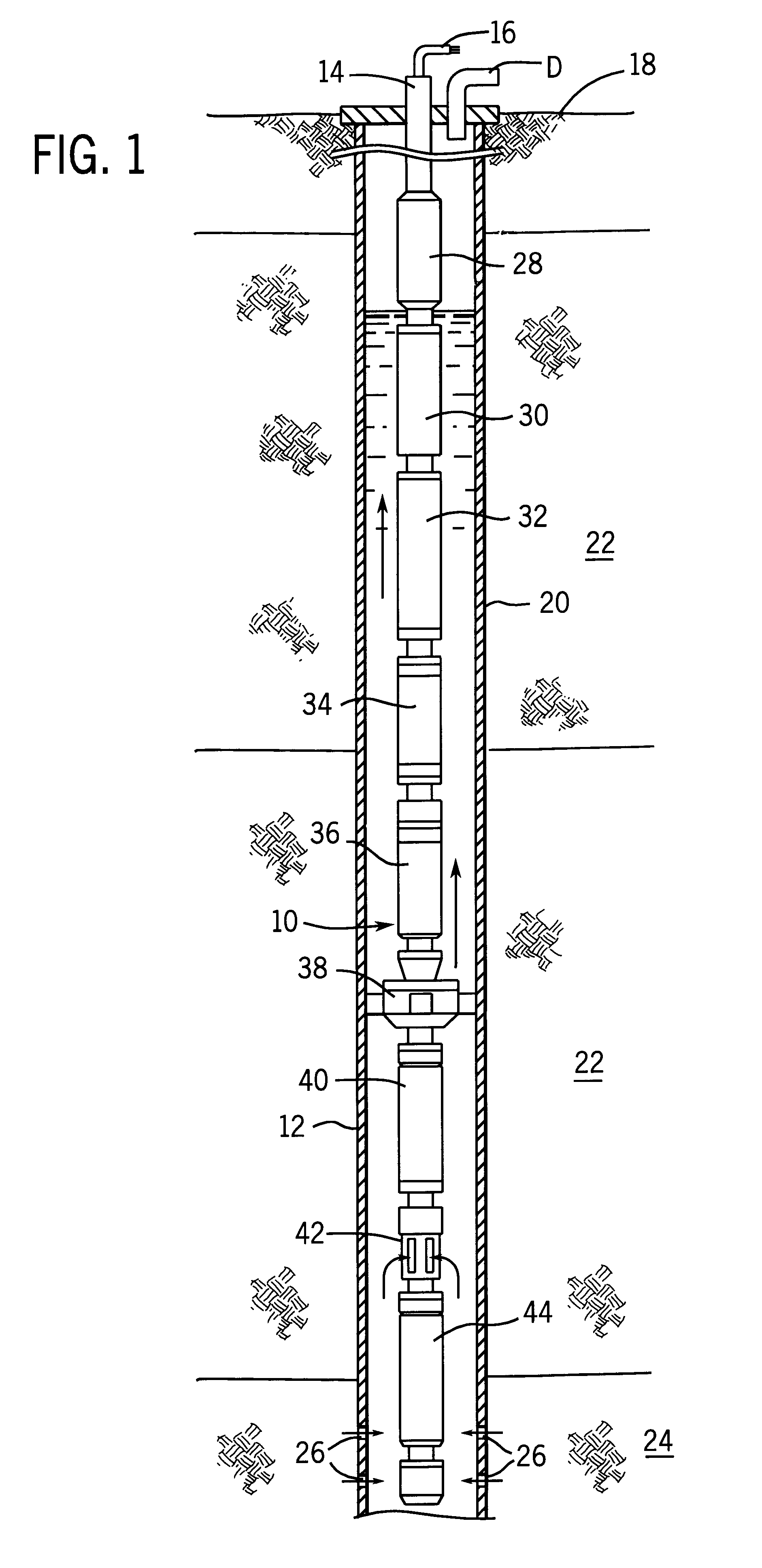
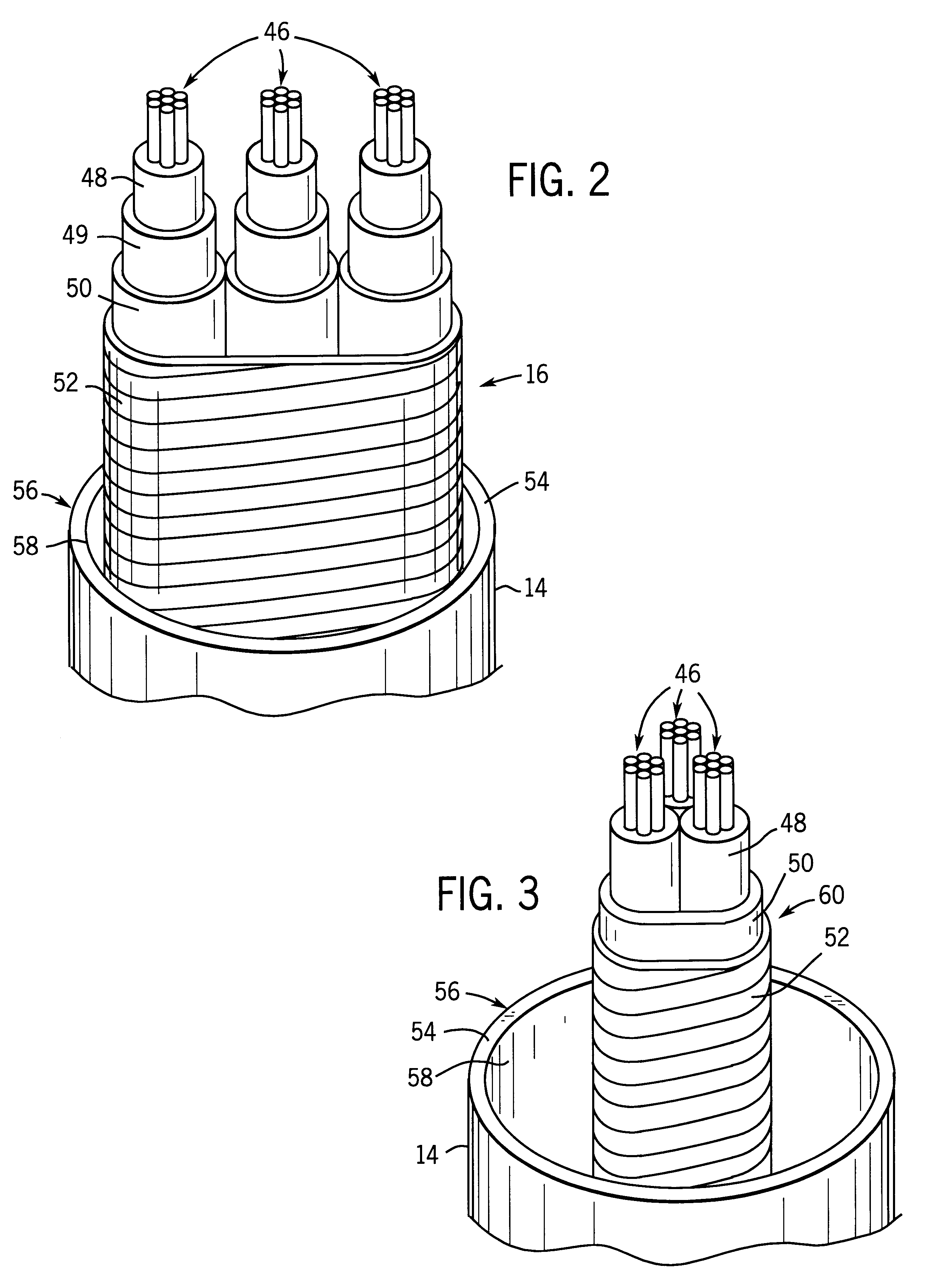
Turning now to the drawings and referring first to FIG. 1, a coiled tubingdeployed pumping system is illustrated diagrammatically and designated generally by the reference numeral 10. Pumping system 10 is deployed in a production well 12 for raising production fluids, such as oil, gas, paraffin, or other minerals of interest to the earth's surface. Pumping system 10 is suspended in well 12 by means of a length of coiled tubing 14. A cable assembly 16 is positioned in coiled tubing 14 for transmitting electrical power to the pumping system as well as for transmitting control and data signals between the pumping system and above-ground equipment. Coiled tubing 14 and cable assembly 16 terminate at a location above the earth's surface 18, where interfacing retention hardware and circuitry (not shown) will generally be located. As will be apparent to those skilled in the art, the coiled tubing-deployed pumping system illustrated in FIG. 1 may also be positioned at a location beneath a b...


PUM


Abstract

A technique for installing a length of cable assembly and coiled tubing includes application of both compressive and tensile forces on the cable assembly. The compressive forces are applied to the cable assembly in a compression station at an entry end of the coiled tubing. Tensile forces are applied to the cable assembly by a wire line or a similar structure situated at an exit end of the coiled tubing. Following installation of the cable assembly in the coiled tubing, the coiled tubing may be transported to an application site, and coupled to equipment, such as a submersible pumping system. The submersible pumping system may then be deployed by extension of the coiled tubing and cable assembly. Additional lengths may be obtained by joining subassemblies formed by the tensile and compressive force technique. The technique reduces residual elongation or strain in the cable assembly as compared to conventional methods.

Description

1. Field of the InventionThe present invention relates generally to devices and techniques for installing cable, such as power cable, into coiled tubing such as for use in delivering electrical power to submerged machinery in a petroleum well. More particularly, the invention relates to a novel technique for installing lengths of cable in coiled tubing by at least partially placing the cable or cable shielding under compressive loading at an entry end of the coiled tubing.2. Description of the Related ArtA number of applications exist wherein power or data signals must be supplied to remote subsea or subterranean locations, such as to drive or control underground equipment. For example, in the field of petroleum extraction and exploitation, it is commonplace to form a wellbore that penetrates a number of subterranean zones, including one or more zones of interest. The zones of interest commonly include geological horizons bearing minerals, such as petroleum, gas, paraffin, and so fo...

Claims


Application Information

Patent Timeline
Patent Type & Authority Patents(United States)
IPC IPC(8): E21B17/00E21B17/20H02G1/08
CPCE21B17/206H02G1/08
Inventor KOBYLINSKI, LEE S.
Owner CAMCO INT
Why Eureka
Try Eureka