
Swirling flashback arrestor

a flashback arrestor and swirling technology, which is applied in the direction of combustion using lumps and pulverulent fuels, combustion types, lighting and heating apparatuses, etc., can solve the problems of flashback events that affect the flow direction of the primary combustion zone to the fuel source, the flashback event can damage the swirler, and the heat of combustion within the flame front has the potential to damage numerous structures within the fuel/air-mixing region of the combustor. , the effect o

Inactive Publication Date: 2001-01-30
PRECISION COMBUSTION
View PDF15 Cites 111 Cited by
  • Summary
  • Abstract
  • Description
  • Claims
  • Application Information

AI Technical Summary

Benefits of technology

The invention can further incorporate a flow conditioner. A flow conditioner, a third monolith, can be added upstream of the swirler flashback arrestor unit, with a gap existing between the conditioner and the arrestor unit. The conditioner has the function of organizing the flow field into the arrestor to reduce or eliminate random fluid flow vectors in the flow stream within the distance of the gap. Flashback is more difficult to arrest in highly skewed flows due to local low-flow velocity regions. Flashback becomes more difficult to arrest as the local channel velocity approaches the laminar flame speed. To maximize performance of the arrestor, the channels in the conditioner are oriented to complement the orientation of the channels in the most upstream monolith of the arrestor.

Problems solved by technology

Flashback within a gas turbine can be a catastrophic event A flashback event occurs when the flame front within the primary combustion zone of a gas turbine combustor moves upstream from the primary combustion zone toward the source of the fuel to an undesired degree.
When such an event occurs, the heat of combustion within the flame front has the potential to damage numerous structures within the fuel / air-mixing region of the combustor.
Thus during a flashback event, the flame front will pass through the swirler before being arrested, thereby causing potential damage to the swirler, especially should flames be held off the swirl vane surfaces after the flashback event has been arrested.
The direction of flow in a flashback event, from the primary combustion zone to the fuel source, is considered abnormal and / or undesired.
If excess bypass is present the device will not function properly, since unarrested flames could bypass the device resulting in damage to the engine.
Flashback is more difficult to arrest in highly skewed flows due to local low-flow velocity regions.
Flashback becomes more difficult to arrest as the local channel velocity approaches the laminar flame speed.

Method used


Image

  • Swirling flashback arrestor
  • Swirling flashback arrestor
  • Swirling flashback arrestor

Examples


Embodiment Construction

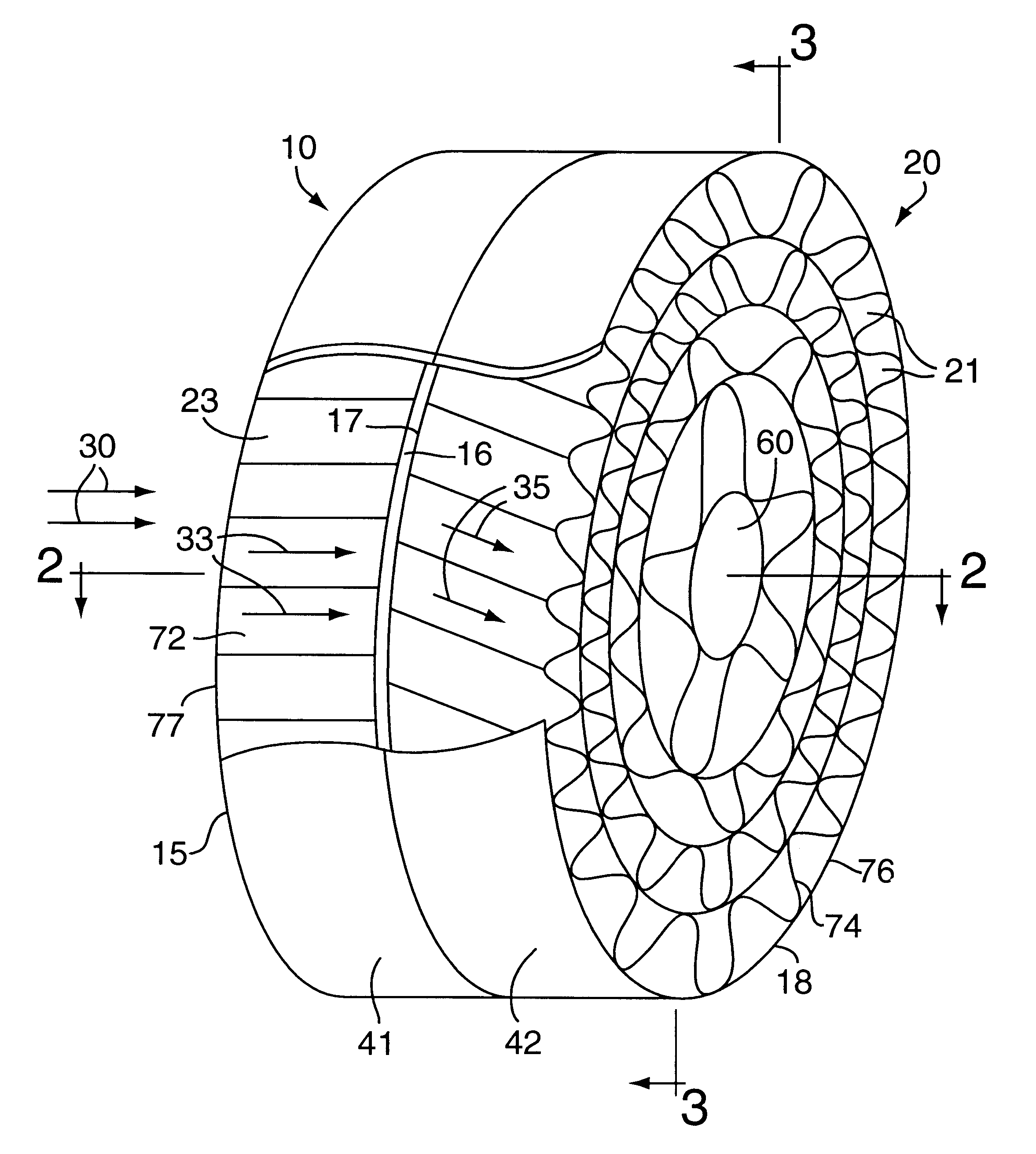
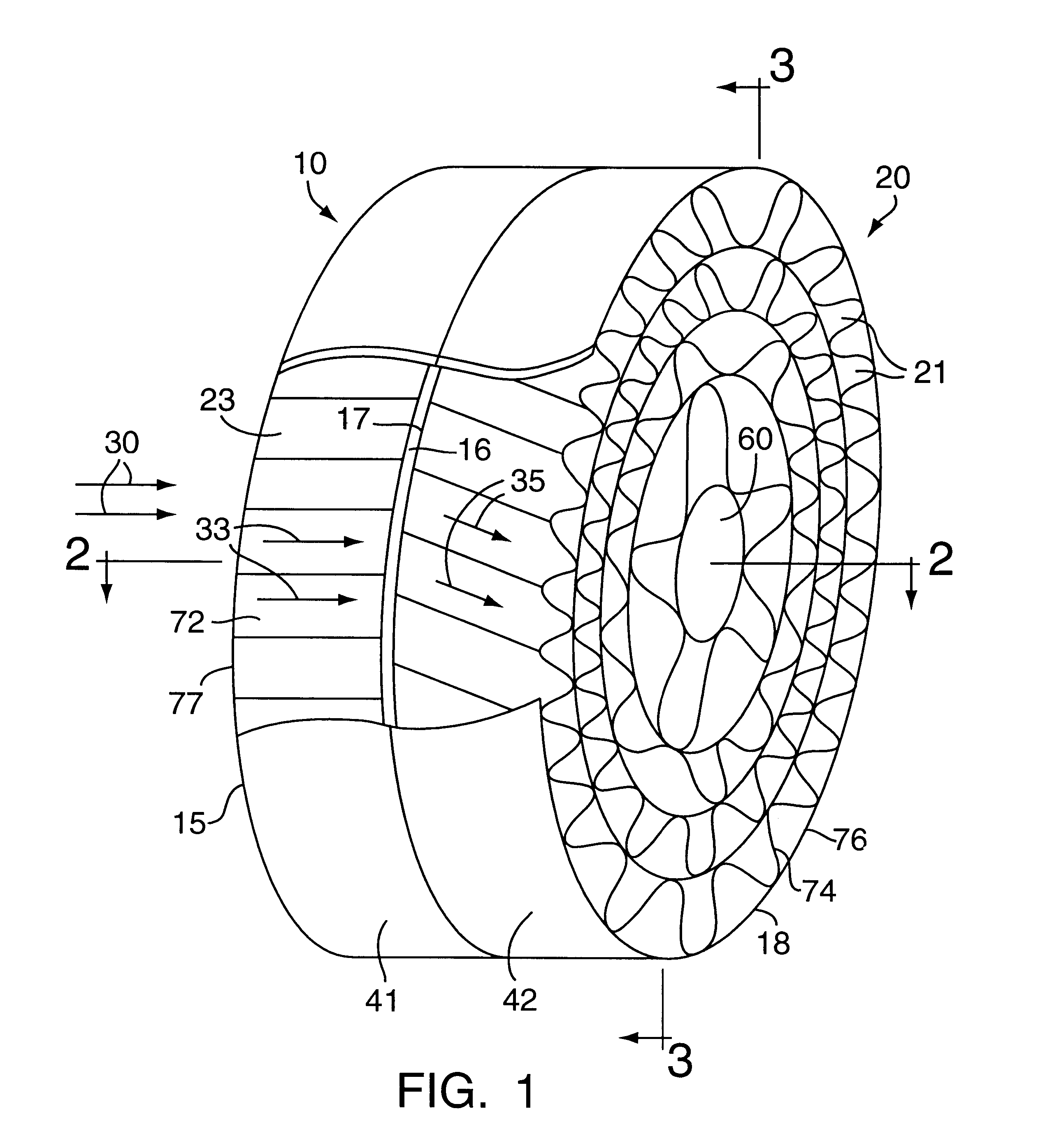
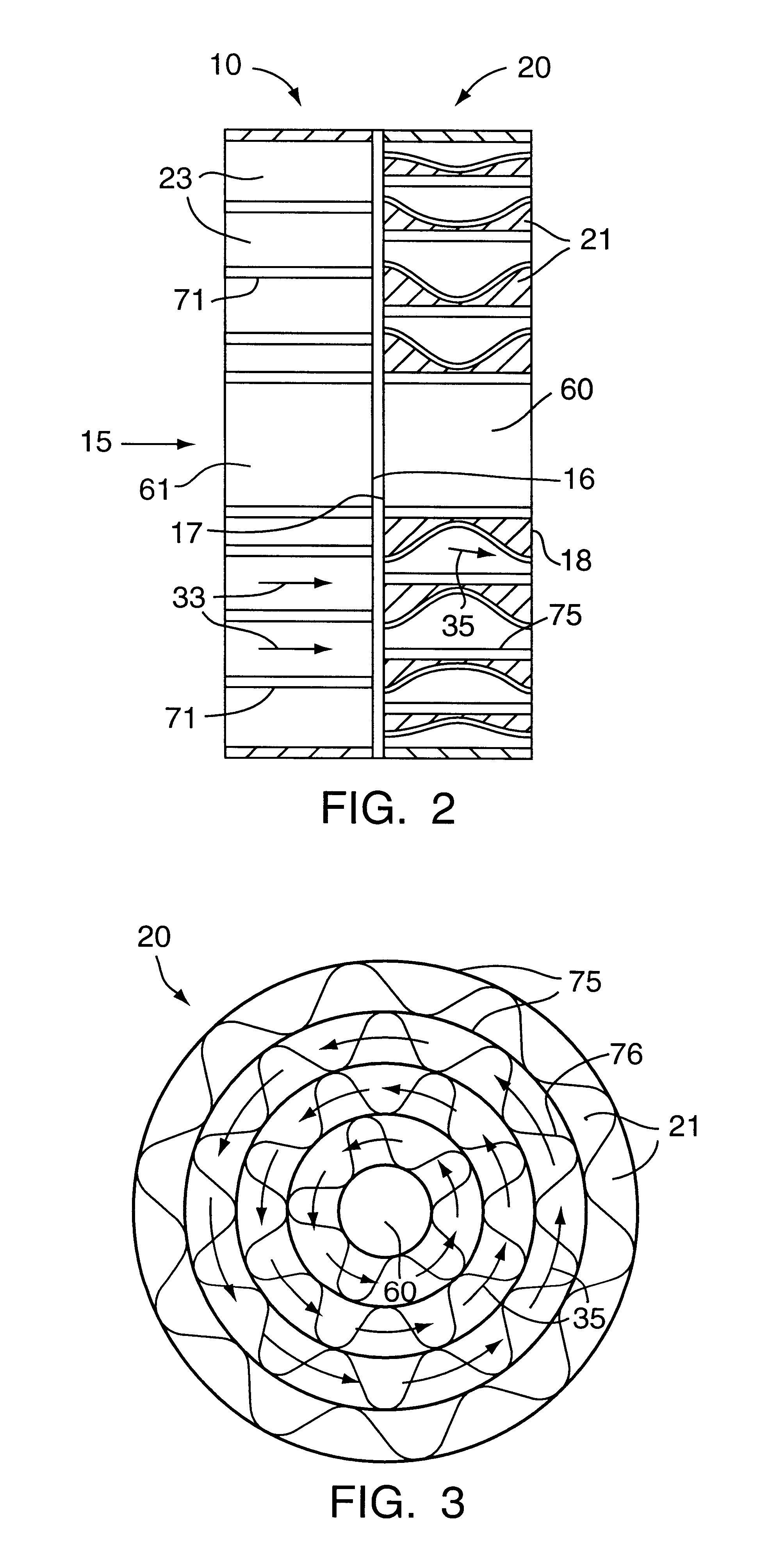
FIG. 1 is an isometric view of a swirler flashback arrestor. The arrestor consists of a downstream monolith 20 and an upstream monolith 10. The orientations of upstream and downstream are based on normal and desired direction of fluid flow 30 through the arrestor, from the fuel source to the combustion region. The depicted fluid flow 30 is parallel, approximately perpendicular the upstream monolith face 15. The fluid enters channels 23 through upstream face 15. In this embodiment, the channels 23 in upstream monolith 10 are non-swirling; therefore a fluid traversing the channel 23 would adopt flow direction 33, which is unchanged from flow direction 30.

After exiting channels 23 through downstream face 16, the fluid enters channels 21 through upstream face 17. It is a requirement of the invention that at least one channel 21 in downstream monolith 20 have a flow path that imparts, or retains, a swirl component to the fluid that traverses the channel. In the depicted embodiment, all c...


PUM


Abstract

A structure is disclosed that will quench a flame front during a flashback event in a gas turbine while simultaneously providing a mixing function during normal operations. The device disclosed consists of two monoliths one upstream of the other. In the basic embodiment of the invention the downstream monolith acts as a mixer while the combination of the upstream monolith and the downstream monolith act as the flashback arrestor. Other embodiments of the device also allow the downstream monolith to be a flameholder.

Description

FIELD OF THE INVENTIONThis invention relates to a structure for mixing a fuel and an oxidant Specifically, the invention is a swirler with an integral flashback arresting capability. In one application, the invention is positioned in a gas turbine combustor downstream of the fuel / air-mixing region and upstream of the primary combustion zone to assist in mixing the fuel and air while simultaneously providing protection from a flashback event. In another aspect of the invention, the invention can also have a flame holding capability.BRIEF DESCRIPTION OF THE RELATED ARTFlashback within a gas turbine can be a catastrophic event A flashback event occurs when the flame front within the primary combustion zone of a gas turbine combustor moves upstream from the primary combustion zone toward the source of the fuel to an undesired degree. When such an event occurs, the heat of combustion within the flame front has the potential to damage numerous structures within the fuel / air-mixing region ...

Claims


Application Information

Patent Timeline
IPC IPC(8): F23D14/82F23R3/02F23R3/28F23R3/40F23R3/18F23R3/00F23D14/72
CPCF23D14/82F23R3/18F23R3/286F23R3/40F23D2209/10
Inventor KRAEMER, GILBERT O.BERRY, JONATHAN DWIGHT
Owner PRECISION COMBUSTION
Learn More