
Liquid crystal display having optical compensatory sheet with negative uniaxial property and an optical axis parallel to the plane of the sheet

a technology of negative uniaxial properties and liquid crystal displays, which is applied in the direction of optics, instruments, polarising elements, etc., can solve the problem that the ips mode lcd cannot be replaced in all respects, and achieve the effect of greatly improving the viewing angle characteristics

Inactive Publication Date: 2001-02-06
FUJIFILM CORP
View PDF15 Cites 85 Cited by
  • Summary
  • Abstract
  • Description
  • Claims
  • Application Information

AI Technical Summary

Benefits of technology

In IPS mode LCD mentioned above, the liquid crystal molecules are scarcely tilted to a plane perpendicular to the substrates of LCD, and therefore viewing angle characteristics are greatly improved. The inventors have found, however, that when the IPS mode LCD is viewed in the specific oblique direction, reversion of gradation and coloration are produced not to enlarge viewing angle in the specific direction. Thus, a CRT cannot be replaced in all respects by the IPS mode LCD, unless the above problems (reversion of gradation and coloration) are resolved.
It is a object of the invention to provide a liquid crystal display provided with an optical compensatory sheet which shows high contrast in an enlarged viewing angle and is almost free from reversion of gradation and coloration in an enlarged viewing angle.
The liquid crystal display provided with the specific optical compensatory sheet according to the invention shows high contrast in an enlarged viewing angle and is almost free from reversion of gradation and coloration in an enlarged viewing angle. Therefore, CRT can be replaced by the liquid crystal display.
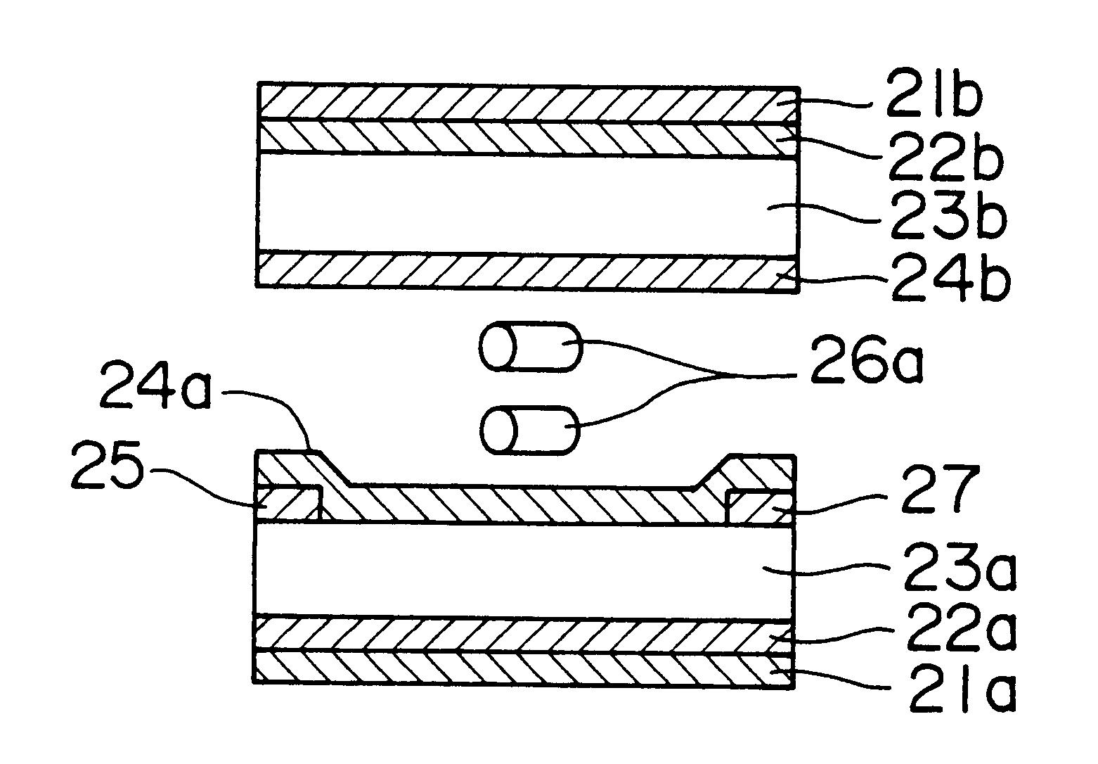
In IPS mode shown in FIG. 2, switching of the direction of liquid crystal molecule within a plane parallel to the substrate is conducted. Therefore, variation of retardation depending upon viewing angle in the liquid crystal layer is greatly reduced, which results in enlarged viewing angle.
FIG. 3 indicates that the light in various directions passed through the liquid crystal layer 32 is compensated by the optical compensatory sheet 31. Therefore, the light entered from the above-mentioned specific direction showing non-uniform variation of retardation is also compensated by the optical compensatory sheet 31. Thus, the use of the optical compensatory sheet of the invention gives the liquid crystal display having an enlarged viewing angle equal to that of CRT, in which leak of light does not occur when black display is viewed from various directions.

Problems solved by technology

Thus, a CRT cannot be replaced in all respects by the IPS mode LCD, unless the above problems (reversion of gradation and coloration) are resolved.

Method used


Image

  • Liquid crystal display having optical compensatory sheet with negative uniaxial property and an optical axis parallel to the plane of the sheet
  • Liquid crystal display having optical compensatory sheet with negative uniaxial property and an optical axis parallel to the plane of the sheet
  • Liquid crystal display having optical compensatory sheet with negative uniaxial property and an optical axis parallel to the plane of the sheet

Examples


example 1

Preparation of IPS mode liquid crystal display

The optical compensatory sheet 1 (prepared previously) was bonded onto the one side of the IPS mode liquid crystal cell 1 (prepared previously), and a pair of polarizing sheets each were bonded onto the optical compensatory sheet 1 and onto the other side of the IPS mode liquid crystal cell 1 so as to form crossed nicols, whereby a liquid crystal display (LCD) was prepared.

In the LCD, one of the polarizing sheets was arranged such that its polarization axis and x-axis (shown in FIG. 5) intersected at an angle of 80 degrees, and the other of the polarizing sheets was arranged such that its polarization axis and x-axis intersected at an angle of -10 degrees. The optical compensatory sheet was arranged between the liquid crystal cell and the polarizing sheet whose polarization axis and x-axis intersected at an angle of 80 degrees, such that its optic axis and x-axis intersected at an angle of 80 degrees.

[Evaluation of liquid crystal display...

example 2

Preparation of IPS mode liquid crystal display

The optical compensatory sheet 2 (prepared previously) was bonded onto both sides of the IPS mode liquid crystal cell 1 (prepared previously), and a pair of polarizing sheets each were bonded onto the optical compensatory sheets 2 provided on both sides of the IPS mode liquid crystal cell 1 so as to form crossed nicols, whereby a liquid crystal display (LCD) was prepared.

In the LCD, one of the polarizing sheets was arranged such that its polarization axis and x-axis (shown in FIG. 5) intersected at an angle of 80 degrees, and the other of the polarizing sheets was arranged such that its polarization axis and x-axis intersected at an angle of -10 degrees. Both optical compensatory sheets were arranged such that both optic axes and x-axis intersected at an angle of 80 degrees.

[Evaluation of liquid crystal display]

Voltage of a rectangular wave of 55 Hz (on-voltage and off-voltage) was applied to the LCD in the same manner as in Example 1.

In...

example 3

Preparation of IPS mode liquid crystal display

The optical compensatory sheet 3 (prepared previously) was bonded onto one side of the IPS mode liquid crystal cell 2 (prepared previously), and a pair of polarizing sheets each were bonded onto the optical compensatory sheet 3 and onto the other side of the IPS mode liquid crystal cell 2 so as to form crossed nicols, whereby a liquid crystal display (LCD) was prepared.

In the LCD, one of the polarizing sheets was arranged such that its polarization axis and x-axis (shown in FIG. 6) intersected at an angle of 0 degree, and the other of the polarizing sheets was arranged such that its polarization axis and x-axis intersected at an angle of 90 degrees. The optical compensatory sheet 3 was arranged such that the optic axis of the discotic layer on the liquid crystal cell side of the five discotic layers was parallel to the rubbing direction of the glass plate (of the liquid crystal cell) faced to the discotic layer.

[Evaluation of liquid crys...


PUM


Abstract

A liquid crystal display is composed of a liquid crystal cell which comprises a pair of transparent substrates at least one of which is provided with an electrode thereon and liquid crystal sealed therebetween, a polarizing sheet arranged on at least one side of the cell, the liquid crystal aligning parallel to a plane of the substrate and varying its direction of molecular major axis in a plane parallel to the plane of the substrate under variation of voltage applied to the liquid crystal cell. The liquid crystal display has an optical compensatory sheet between at least one side of the liquid crystal cell and the polarizing sheet, the optical compensatory sheet having an optically negative uniaxial property and an optic axis parallel to a plane of the sheet.

Description

1. Field of the InventionThe present invention relates to a liquid crystal display which is improved in viewing angle characteristics.2. Description of Prior ArtAs a display for electronic office system-devices such as a desk-top personal computer and a word processor, CRTs (cathode ray tube) have been employed so far. Recently, a liquid crystal displays (hereinafter referred to as LCD) are widely employed instead of the CRTs because of their small thickness, light weight and low power consumption. The LCD, however, does not have good display characteristics (especially enlarged viewing angle) equal to those of CRT. The LCD generally has a structure that a liquid crystal cell is disposed between a pair of polarizing sheets. Most of LCDs use a twisted nematic liquid crystal. The operational modes of LCD using the twisted nematic liquid crystal are roughly divided into a birefringence mode and an optical rotatory mode.A super twisted nematic liquid crystal display (hereinafter referre...

Claims


Application Information

Patent Timeline
IPC IPC(8): G02F1/13G02F1/1343G02F1/133G02B5/30G02F1/1335G02F1/13363
CPCG02F1/134363G02F1/133634G02F2413/14
Inventor MORI, HIROYUKINAKAMURA, TAKU
Owner FUJIFILM CORP
Learn More