Air lock for introducing substrates to and/or removing them from a treatment chamber

Inactive Publication Date: 2001-03-06
APPLIED MATERIALS GMBH & CO KG
View PDF29 Cites 32 Cited by
  • Summary
  • Abstract
  • Description
  • Claims
  • Application Information

AI Technical Summary

Benefits of technology

A particularly simple design of the air lock results wherein the air lock comprises a carrousel lock formed essentially of a carrousel housing and a lock chamber wheel seated so as to be able to rotate in the carrousel housing. Individual lock chambers whose individual openings are accessible in the radial direction are inserted or formed into the lock chamber wheel on the periphery. The carrousel housing constituting the transfer channel has sealing devices at its periphery which make sealing contact with the inside wall of the transfer channel during material transport, whereby the individual chambers are atmospherically separated from one another and, for instance, from the atmospheric spaces having different atmospheric pressures. It has prove

Problems solved by technology

This sharply restricts the use of this known air lock in regard to

Method used


Image

  • Air lock for introducing substrates to and/or removing them from a treatment chamber
  • Air lock for introducing substrates to and/or removing them from a treatment chamber
  • Air lock for introducing substrates to and/or removing them from a treatment chamber

Examples


Embodiment Construction

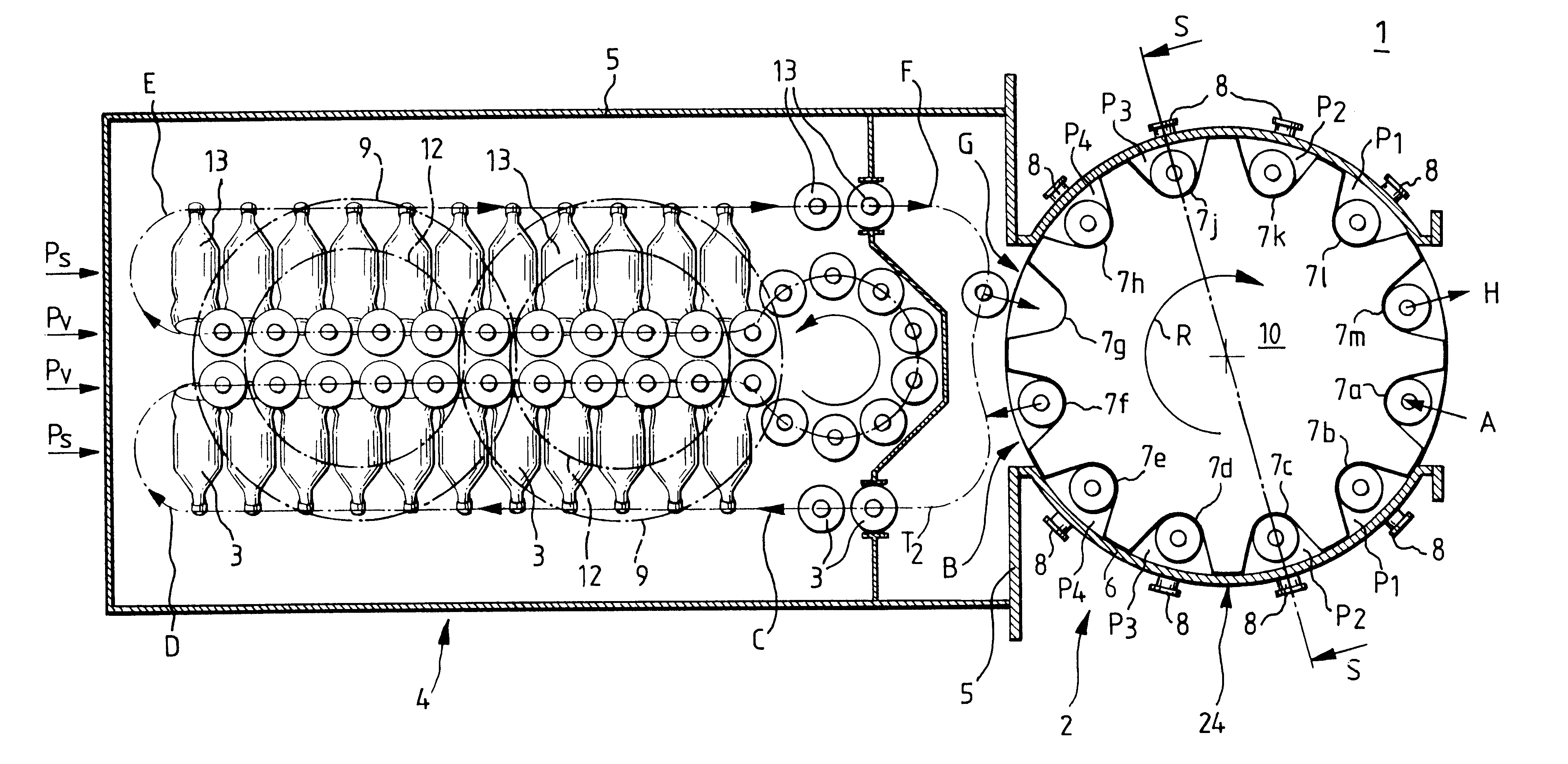
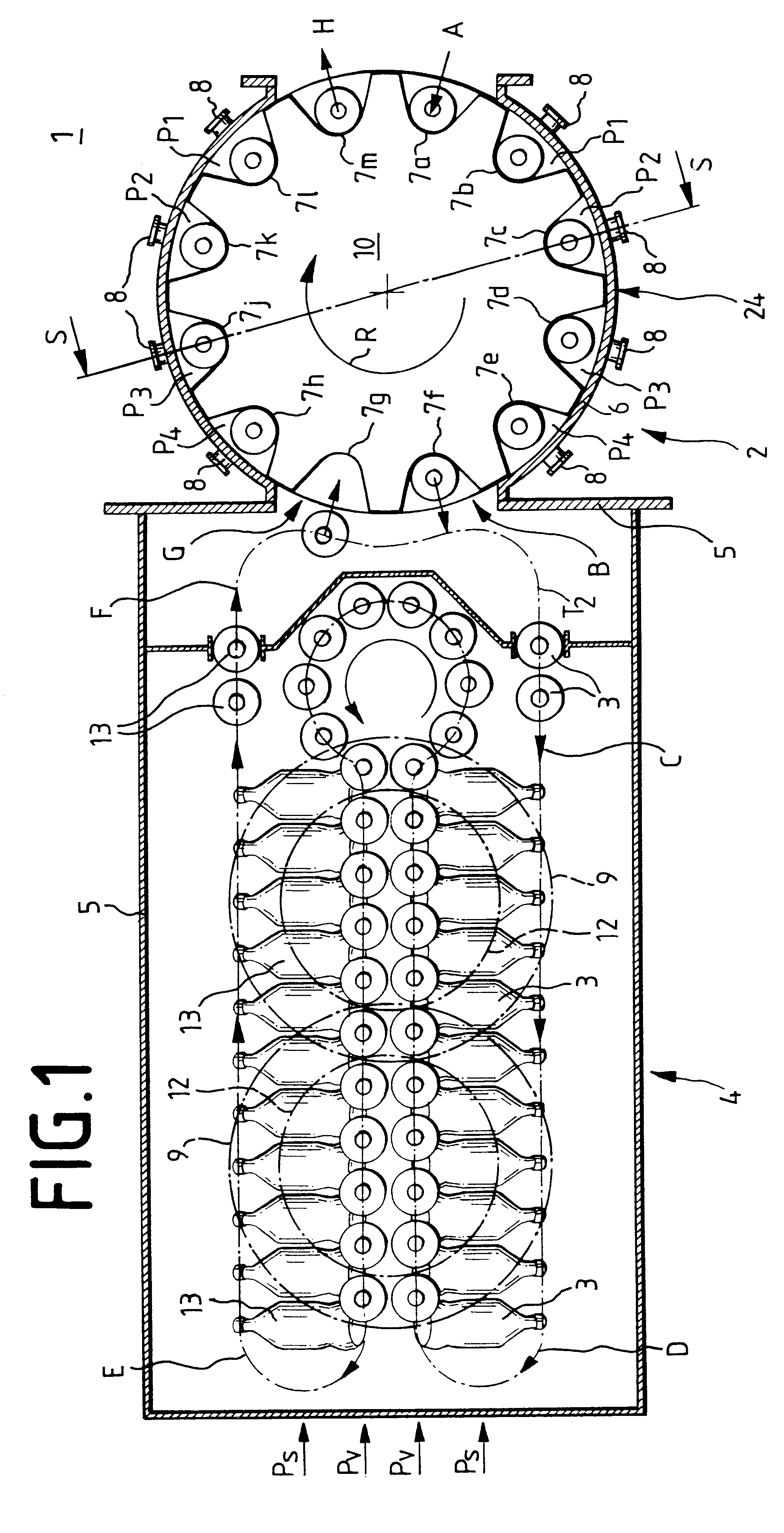
Referring to FIG. 1, the air lock 2 for continuous introduction and / or removal of workpieces in and / or from atmospherically separated spaces 1,4 comprises a transfer channel 6 constructed as a carrousel housing 24 and connecting a treatment space 4 for processing the substrates 3,13 to the exterior 1. The air lock 2 comprises, alongside the carrousel housing 24, a lock chamber wheel 10 seated therein free to rotate, in which individual lock chambers 7a-7m are built on the periphery and equally spaced from one another.

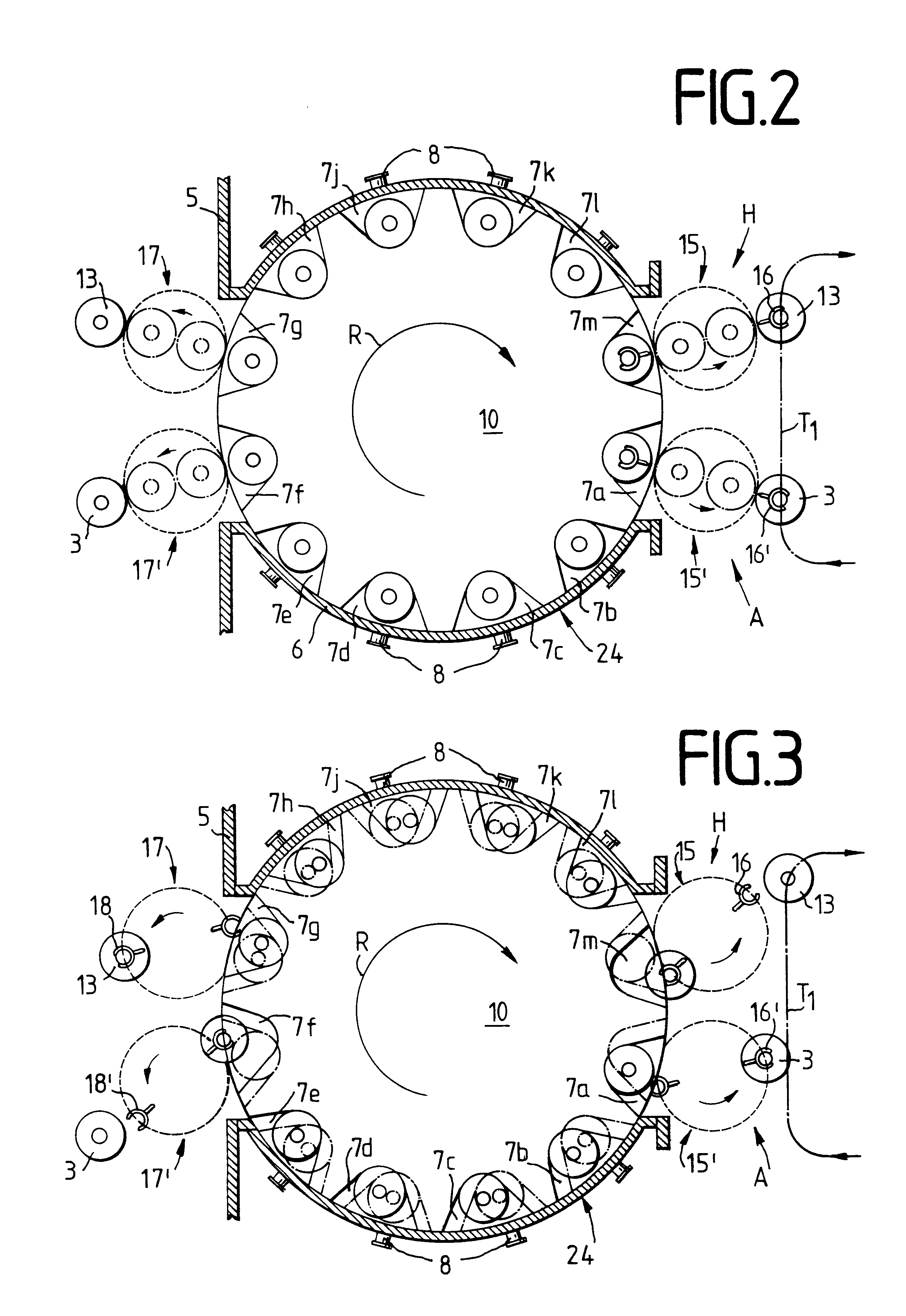
For transferring the workpieces 3 from the exterior 1 into the treatment space 4, the individual workpieces 3 in the loading station A drawn in FIGS. 2-7 are brought via the transport path T.sub.1 (see FIG. 2) to the loading station A arranged in the exterior 1. The loading station A comprises a handling mechanism for transfer action 15' with which a gripping device 16' is associated. By means of the gripping device 16', the substrate 3 brought up via the transport path...


PUM

PropertyMeasurementUnit
Lengthaaaaaaaaaa
Pressureaaaaaaaaaa

Abstract

In an air lock for continuous introduction into and/or removal of workpieces from spaces (1,4) separated atmospherically, the individual substrates (3,13) are transported through a transfer channel (24). At least one lock chamber (7a-7m) serving to accommodate the substrates (3,13) is arranged movably in the transfer channel (24). During the substrate transport in the transfer channel (24), the lock chamber (7a-7m) is atmospherically separated both from the exterior (1) having normal pressure and from the coating chamber (4). The air lock (2) includes a carrousel lock which has a carrousel housing (24) and a lock chamber wheel (10). On the periphery in the lock chamber wheel (10) individual lock chambers (7a-7m) are provided, in which the workpieces (3,13) to be brought into the chamber to be loaded (4) are inserted freely accessible on the normal pressure side. By turning the lock chamber wheel (10), the substrates (3,13) in the lock chambers (7a-7m) are transported from the coating station (A) to the transfer station (B) into the treatment chamber (4) diametrically opposite the normal pressure side. In the transfer station (B) the substrates (3,13) are removed from the transfer channels (7a-7m) by means of a transfer device (17') and are available for further treatment in the treatment chamber (4). The treatment chamber (4) includes, for instance, of a vacuum-coating chamber in which the workpieces (3,13) as the substrates to be coated are coated by a vacuum-supported coating method.

Description

INTRODUCTION AND BACKGROUNDThe present invention pertains to an air lock for introducing workpieces to and / or removing them from atmospherically separated chambers with at least one transfer channel connecting the chambers.Air locks of this class are known, for instance, from German Patent Application No. P 27 47 061. This conventional air lock serves to introduce endless carrier belts which are to be coated in a vacuum chamber by means of the air lock from the surrounding outer area having normal pressure into the coating chamber and removing them from the coating chamber after the coating process is finished. The pressure difference between the external atmospheric pressure and the usual vacuum pressure for vacuum-supported coating processes of at most 10.sup.-3 mbar is maintained over a pressure stage path which features several shutters arranged in succession, through which the carrier belt is guided. Essential elements of these so-called belt transfer channels, which bridge the...

Claims


Application Information

Patent Timeline
IPC IPC(8): C03C17/00C23C14/56C23C16/54B05B13/02B01J3/02B65G47/84B65G49/00
CPCC23C14/56C23C16/54B65G21/00
Inventor BAUMECKER, TOMASGRIMM, HELMUTHENRICH, JURGENMICHAEL, KLAUSRODLING, GERTULRICH, JURGEN
Owner APPLIED MATERIALS GMBH & CO KG
Why Eureka
Try Eureka