Ultrasonic imaging device with integral display

an ultrasonic imaging and display technology, applied in the field of medical devices and methods, can solve the problem of inconvenient plugging in of the devi

Inactive Publication Date: 2001-03-20
FUJIFILM SONOSITE
View PDF6 Cites 147 Cited by
  • Summary
  • Abstract
  • Description
  • Claims
  • Application Information

AI Technical Summary

Problems solved by technology

While it is possible to configure the device for powering through an external sour

Method used


Image

  • Ultrasonic imaging device with integral display
  • Ultrasonic imaging device with integral display
  • Ultrasonic imaging device with integral display

Examples


Embodiment Construction

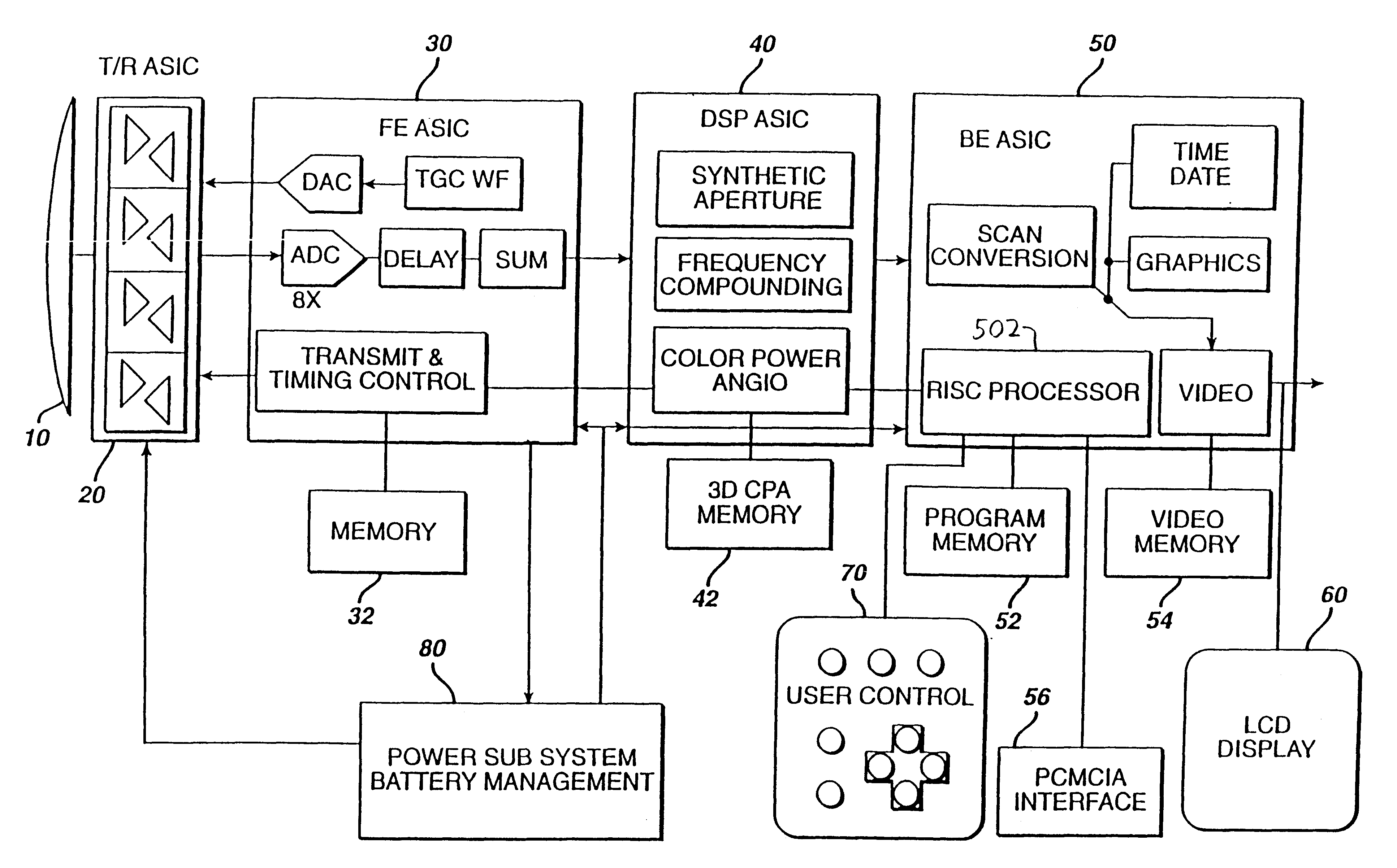
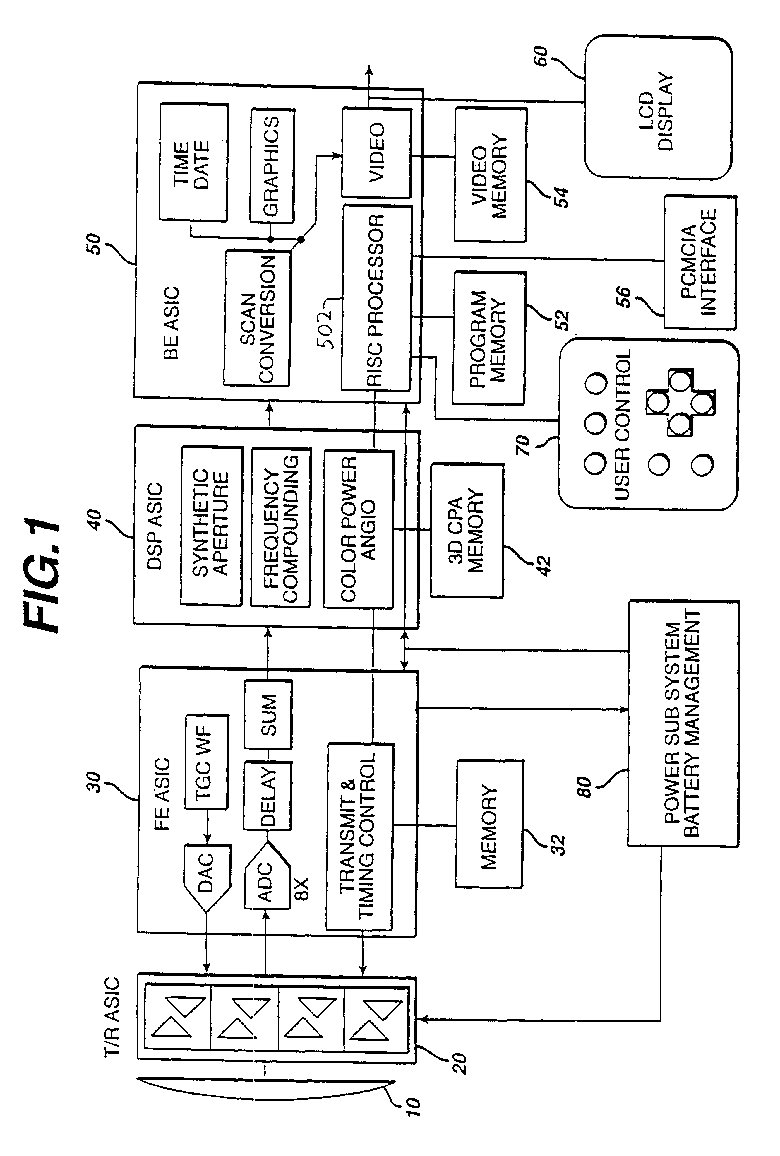
Referring first to FIG. 1, the architecture of a hand held ultrasound system of the present invention is shown. It is possible to package an entire ultrasound system in a single hand held unit only through judicious selection of functions and features and efficient use of integrated circuit and ultrasound technology. A transducer array 10 is used for its solid state, electronic control capabilities, variable aperture, image performance and reliability. Either a flat or curved linear array can be used. In a preferred embodiment the array is a curved array, which affords a broad sector scanning field. While the preferred embodiment provides sufficient delay capability to both steer and focus a flat array such as a phased array, the geometric curvature of the curved array reduces the steering delay requirements on the beamformer. The elements of the array are connected to a transmit / receive ASIC 20 which drives the transducer elements and receives echoes received by the elements. The t...


PUM


Abstract

A hand held ultrasonic imaging device is provided as an integral unit with all components and circuitry necessary for both image acquisition and image display included in a single enclosure. Usually, the device will also include an on-board battery so that it can be used without any power cords or other cables. Preferably, the device is provided as part of a system including a recharging base unit having a receptacle for removably receiving and storing the hand held device.

Description

1. Field of the InventionThe present invention relates generally to medical devices and methods and, more particularly to a fully integrated hand held ultrasonic diagnostic instrument.As is well known, modem ultrasonic diagnostic systems are large, complex instruments. Today's premium ultrasound systems, while mounted in carts for portability, continue to weigh several hundred pounds. In the past, ultrasound systems such as the ADR 4000 ultrasound system produced by Advanced Technology Laboratories, Inc. were smaller, desktop units about the size of a personal computer. However, such instruments lacked many of the advanced features of today's premium ultrasound systems such as color Doppler imaging and three dimensional display capabilities. As ultrasound systems have become more sophisticated they have also become bulkier.However, with the ever increasing density of analog and digital electronics, it is now possible to foresee a time when ultrasound systems will be able to be minia...

Claims


Application Information

Patent Timeline
IPC IPC(8): A61B8/00A61B8/14G01S15/89G01S15/00G01S7/523G01S7/521G01S7/529G01S7/52G10K11/34G10K11/00A61B8/06
CPCA61B8/00A61B8/14A61B8/4455G01S7/52028G01S7/5206G01S7/52079G01S7/5208G01S15/892G01S15/899G10K11/004G10K11/345G01S15/8915A61B8/4427A61B8/06A61B8/13A61B2560/0456A61B8/4494
Inventor BUNCE, STEVENPFLUGRATH, LAUREN S.
Owner FUJIFILM SONOSITE
Why Eureka
Try Eureka