Baghouse, long filter assembly and method of installation

a filter assembly and long filter technology, applied in the direction of filtration separation, separation process, dispersed particle separation, etc., can solve the problems of certain barriers to easy replacement of fabric filter bags by pleated elements, inability to install relatively long and rigid pleated elements without considerable manipulation, and inability to operate and structure the same baghous

Inactive Publication Date: 2001-03-20
BHA GROUP HLDG
View PDF17 Cites 53 Cited by
  • Summary
  • Abstract
  • Description
  • Claims
  • Application Information

AI Technical Summary

Problems solved by technology

Although many baghouses are made according to this basic structure, there may be numerous operational and structural differences among baghouses.
However, certain barriers to easy replacement of fabric filter bags by pleated element filters exist.
A relatively long and rigid pleated element filter cannot be installed without considerable manipulations if it can be installed at all, even if the baghouse has a roof with a portion that can be moved to a position which provides access to the clean air plenum.
This presents a problem for filter manufacturers because there are limits as to the width of the filter media that can be p

Method used


Image

  • Baghouse, long filter assembly and method of installation
  • Baghouse, long filter assembly and method of installation
  • Baghouse, long filter assembly and method of installation

Examples


Embodiment Construction

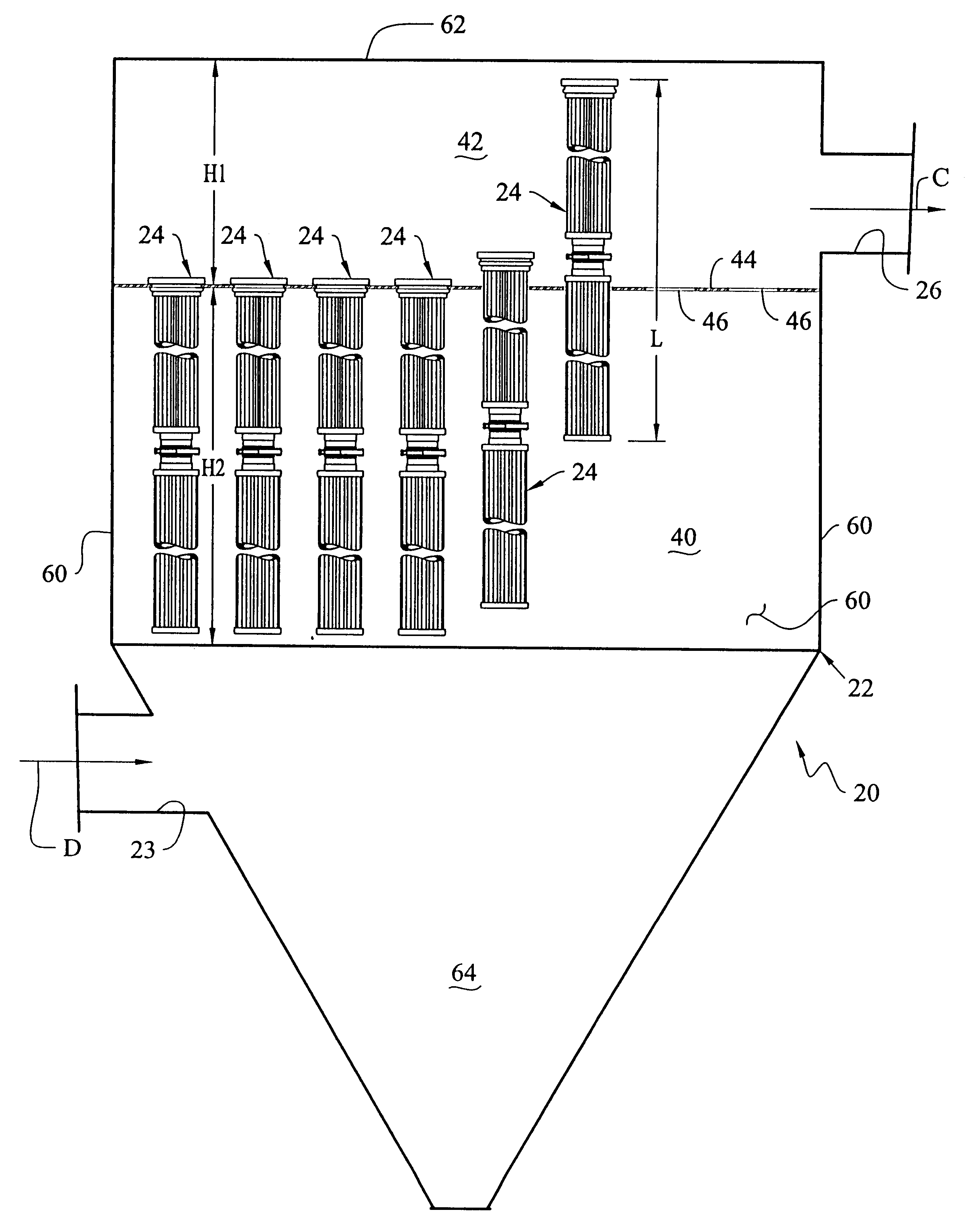
A baghouse 20 according to the present invention is illustrated in FIG. 1. The baghouse 20 is defined by an enclosed housing 22. The housing 22 is made from a suitable material, such as sheet metal. A particulate laden gas D flows through the baghouse 20 from an inlet 23. The particulate laden gas D is filtered by a plurality of filter assemblies 24 (FIG. 2) of the present invention located within the baghouse 20. Cleaned gas C exits through an outlet 26 of the baghouse 20.

The baghouse 20 is divided into a "dirty air" plenum 40 and a "clean air" plenum 42 by a tubesheet 44 made from a suitable material, such as sheet metal. The tubesheet 44 has at least a portion that is substantially planar. The inlet 23 is in fluid communication with the dirty air plenum 40. The outlet 26 is in fluid communication with the clean air plenum 42.

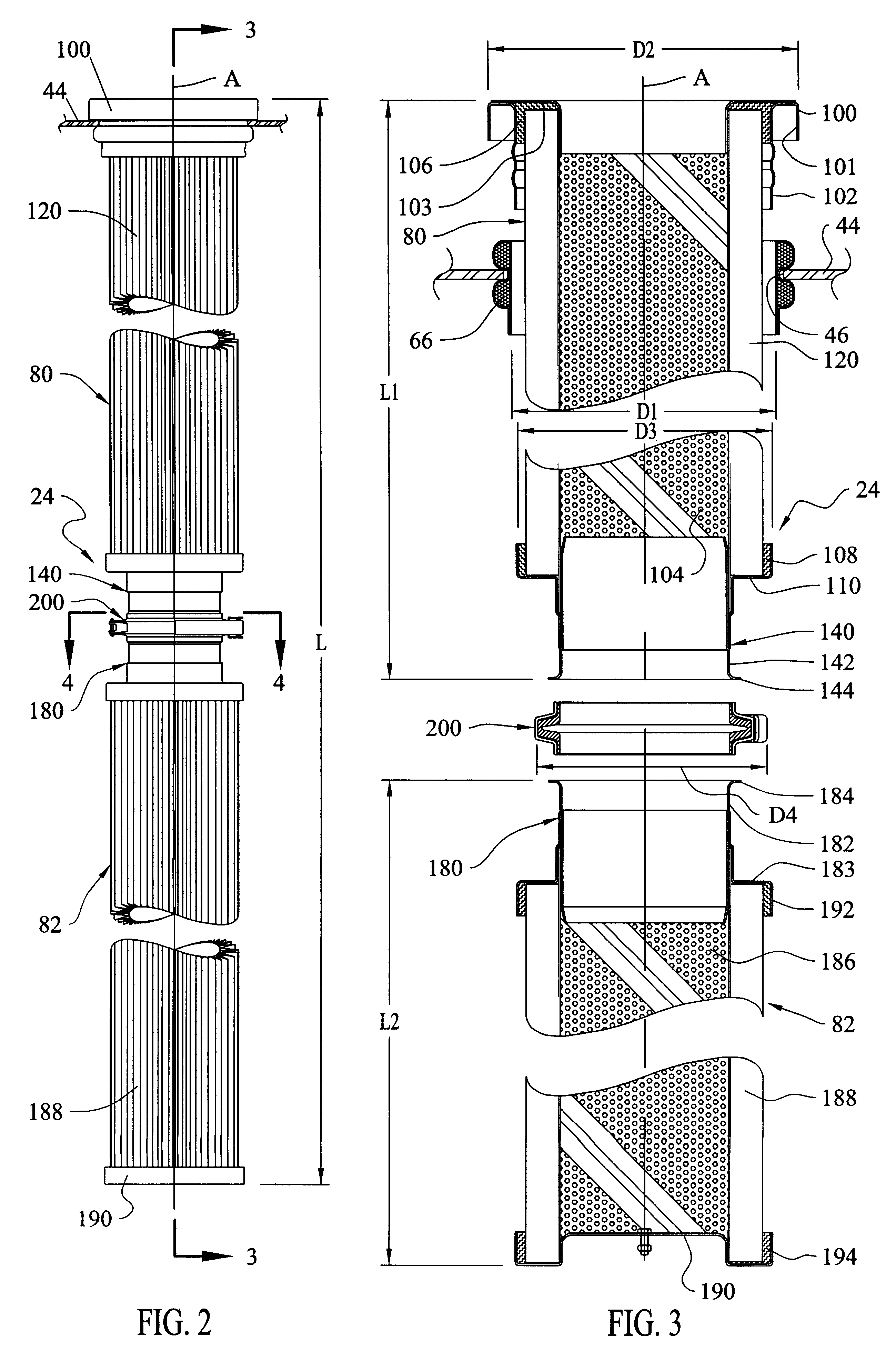
A plurality of openings 46 extend through the planar portion of the tubesheet 44. Each opening 46 has an effective diameter D1 (best seen in FIG. 3), defined...


PUM

PropertyMeasurementUnit
Lengthaaaaaaaaaa
Lengthaaaaaaaaaa
Weightaaaaaaaaaa

Abstract

A filter assembly (24) includes a first filter portion (80) with a first attachment (100) adapted to attach to a tubesheet (44) to support at least a portion of the first filter portion in a second plenum (40) and to permit fluid communication between the first filter portion and a first plenum (42). A tubular member (104) is fixed to and extends from the first attachment (100). A pleated filter element (120) is disposed adjacent to the tubular member (104) for support. A second attachment (140) is fixed to the tubular member (104) at a second end of the first filter portion (80) and defines an opening through which fluid may flow. The tubular member (104) is fixed to the first and second attachments (100, 140) with sufficient strength to support the weight of at least one other filter portion. A second filter portion (82) includes a third attachment (180) at a first end and defines an opening through which fluid may flow. A tubular member (186) is fixed to and extends from the third attachment (180). A pleated filter element (188) is disposed adjacent to the tubular member (186) for support. A plate (190) closes a second end of the second filter portion (82). A clamping mechanism (200, 240) sealingly connects the second attachment (140) of the first filter portion (80) with the third attachment (180) of the second filter portion (82) and permits fluid communication between the first and second filter portions. The clamping mechanism (200, 240) has sufficient strength to support eh weight of filter portions located on the side of the clamping mechanism opposite the first attachment (100) of the first filter portion (80).

Description

1. Technical FieldThe present invention relates generally to a baghouse, a filter assembly for use in the baghouse and a method of installing the filter assembly in the baghouse. In particular, the present invention relates to a relatively long multi-piece filter assembly having pleated filter elements.2. Description of the Prior ArtContinuous emphasis on environmental quality results in ever-increasing regulatory control on pollutants and emissions throughout the world. Much of the regulatory control is focused on reducing pollutants and emissions from certain industrial plants, such as power plants and metal production plants. A known technique to control pollutants and emissions from industrial plants is to separate undesirable particulate matter carried in a gas stream by fabric filtration. Such fabric filtration is accomplished in a dust collection apparatus known in the industry as a "baghouse."The baghouse typically includes a housing divided into two plenums by a tubesheet. ...

Claims


Application Information

Patent Timeline
IPC IPC(8): B01D46/02
CPCB01D46/02B01D46/521B01D2265/028B01D2271/02
Inventor CLEMENTS, JACK THOMASMAHONEY, RONALD LAWAYNEDOEHLA, JAMES ROY
Owner BHA GROUP HLDG
Why Eureka
Try Eureka