Thermal overload mechanism

a technology of overload mechanism and thermal insulation, which is applied in the direction of relays, emergency protective arrangements for limiting excess voltage/current, protective switch details, etc., can solve the problems of adversely affecting delicate telecommunications equipment, injuring personnel, increasing the cost and assembly time of such devices,

Inactive Publication Date: 2001-03-20
COMMSCOPE INC
View PDF14 Cites 18 Cited by
  • Summary
  • Abstract
  • Description
  • Claims
  • Application Information

AI Technical Summary

Problems solved by technology

In the event of a power cross situation, however, which results in the application of high currents and resulting high temperatures to protection mechanisms, a grounding path must also be formed to provide for the discharge of power surges which would, otherwise, adversely affect delicate telecommunications equipment and injure personnel.
The drawback of this technique, however, is that the additional elements (such as the spring and fuseable link) must be added to the protection mechanisms during assembly, thereby increasing the cost and assembly time for such devices.
In the event of a power cross occurrence wherein current resulting in increased heat is applied to the solid state device, the heat will melt or break the back wall membrane of the spacer, causing direct electrical contact between the second spring member and the tip and ring conductors.

Method used


Image

  • Thermal overload mechanism
  • Thermal overload mechanism

Examples


Embodiment Construction

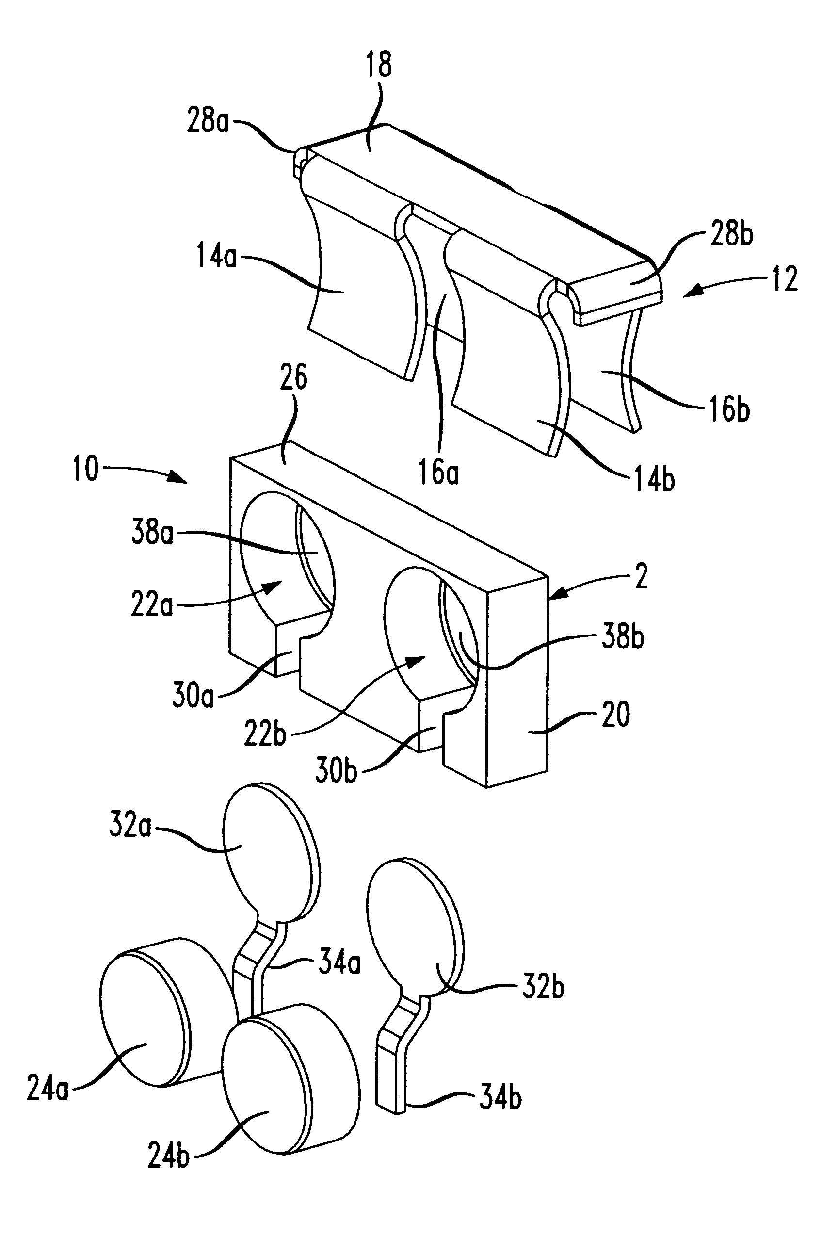
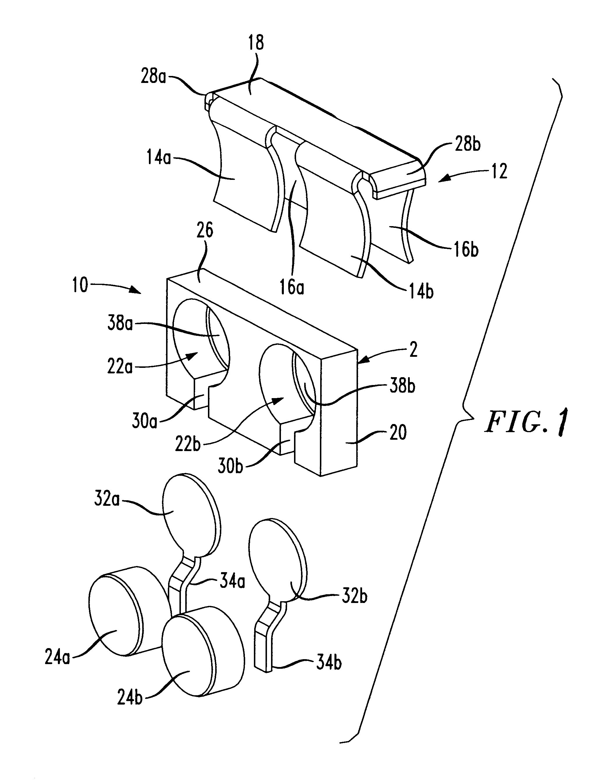
An exploded view of a thermal overload mechanism 10 in accordance with a currently preferred embodiment of the invention is shown as having a clip member 12 constructed of electrically conductive material, such as metal. Clip member 12 includes a pair of front spring members 14a and 14b, and a pair of rear spring members 16a and 16b.The spring members are attached to a clip base 18 which is connected to a common ground (not shown). The spring members are oriented, arranged and biased such that each spring member in each pair is directed to a spring member in the other pair, i.e. so that spring members 14a and 16a are directed toward each other. In this manner, a spring or clamping force is produced against an object placed between the spring member pairs, as explained more fully below.

The thermal overload mechanism 10 further includes a spacer element 20, preferably constructed of a nonelectrically conducting or insulating material such as plastic. The spacer element 20 has a pair o...


PUM


Abstract

A thermal overload mechanism for providing protection to tip and ring conductors in a telecommunications system in the event of a power cross occurrence of telephone lines with power lines. The thermal overload mechanism includes a clip having front and rear spring members dimensioned for seating about a spacer element. The spacer element includes one or more recesses defined therein for accommodating securement of solid state devices. The recesses formed in the spacer elements contain a breachable membrane or wall which is breakable in the event the membrane temperature exceeds a predetermined temperature such as a temperature occurring in the event of a power cross situation. A contact configured for seating within the recess between the membrane and solid state device is provided for maintaining electrical contact with the tip and ring wires. During a power cross situation, high current causes the temperature of the solid state devices increase, thereby causing a breach of the membrane and providing a direct grounding path for the tip and ring wires through the rear spring and common ground.

Description

1. Field of the InventionThe present invention pertains to a protection device for use in the telecommunications field for protecting equipment connected to tip and ring conductor pairs. More particularly, the present invention relates to a thermal overload mechanism for providing a grounding path for tip and ring conductors during a power cross occurrence.2. Description of the Related ArtTelecommunications systems typically employ protection mechanisms such as grounding devices located proximate a service subscriber location or central office to protect telecommunications lines from detrimental power surges and voltage spikes. The voltage spikes are usually caused by lightning striking telephone lines, and the power surges are caused by power crosses between telephone lines and high voltage power cables which occur, for example, as a result of high winds. In particular, grounding devices are used to provide a path to common ground for voltage surges caused by lightning strikes to p...

Claims


Application Information

Patent Timeline
Patent Type & Authority Patents(United States)
IPC IPC(8): H01C7/12H04M3/18
CPCH01C7/123H04M3/18
Inventor KANE, ADAM STUARTPELOSI, WALTER
Owner COMMSCOPE INC
Why Eureka
Try Eureka