Place calibration of sonar receive array

a sonar and receive array technology, applied in the field of sonar receive arrays, can solve the problems of inability to change the hydrophone characteristics of hydrophones after deployment of the array at sea, the detection capabilities of individual hydrophones in the towed array may unpredictably vary, and the calibration technique is extremely tedious

Inactive Publication Date: 2001-03-27
L 3 COMM CORP
View PDF8 Cites 22 Cited by
  • Summary
  • Abstract
  • Description
  • Claims
  • Application Information

AI Technical Summary

Problems solved by technology

Over a period of time, the detection capabilities of individual hydrophones in towed array may unpredictably vary.
However, due to the very large number of discrete hydrophones in an array, which may have a very long length, such calibration technique is extremely tedious.
In addition, such calibration would have to be performed at a shore installation, so that changes in hydrophone characteristics occurring after deployment of the array at sea would not be possible.
In this approach, mult

Method used


Image

  • Place calibration of sonar receive array
  • Place calibration of sonar receive array
  • Place calibration of sonar receive array

Examples


Embodiment Construction

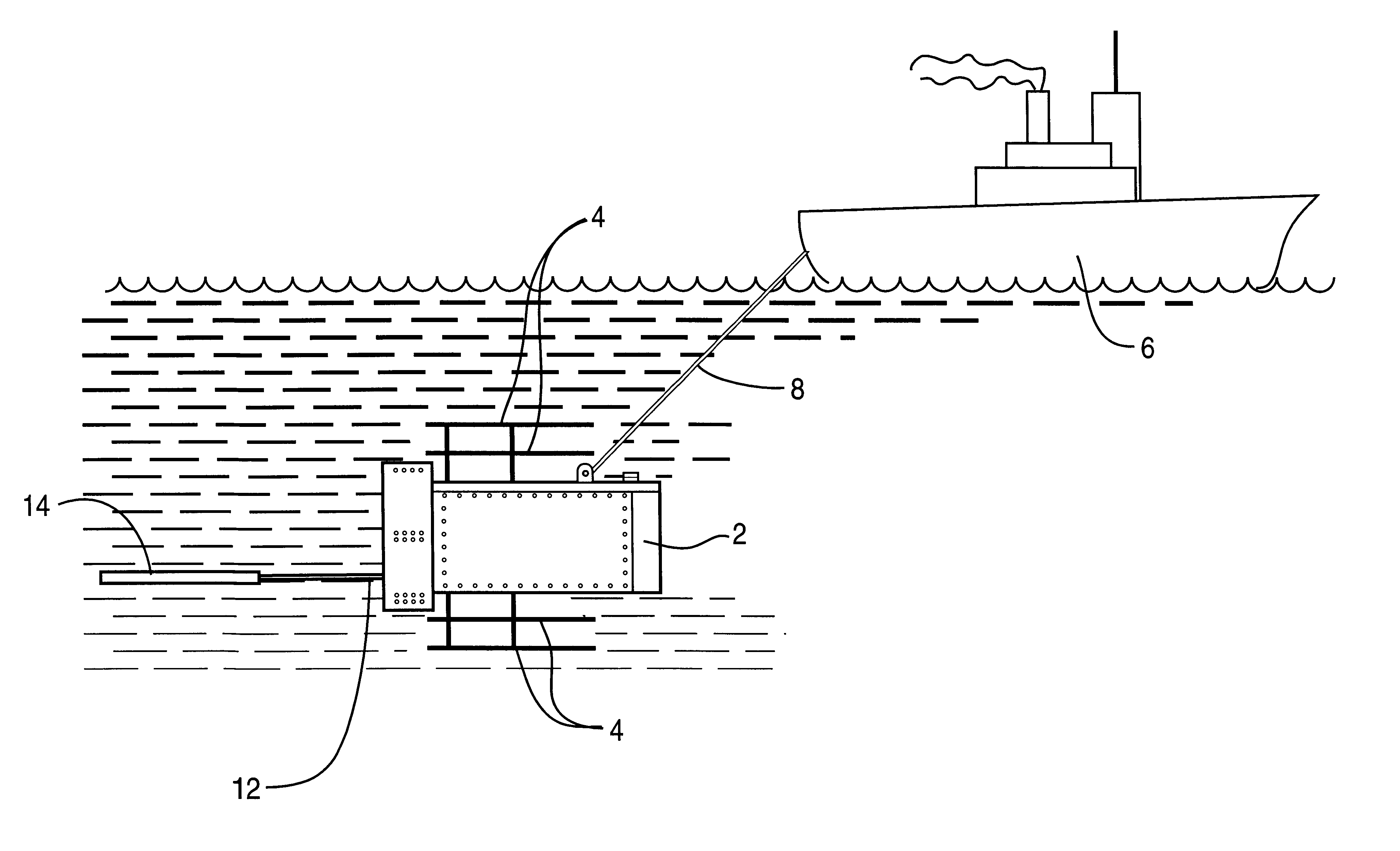
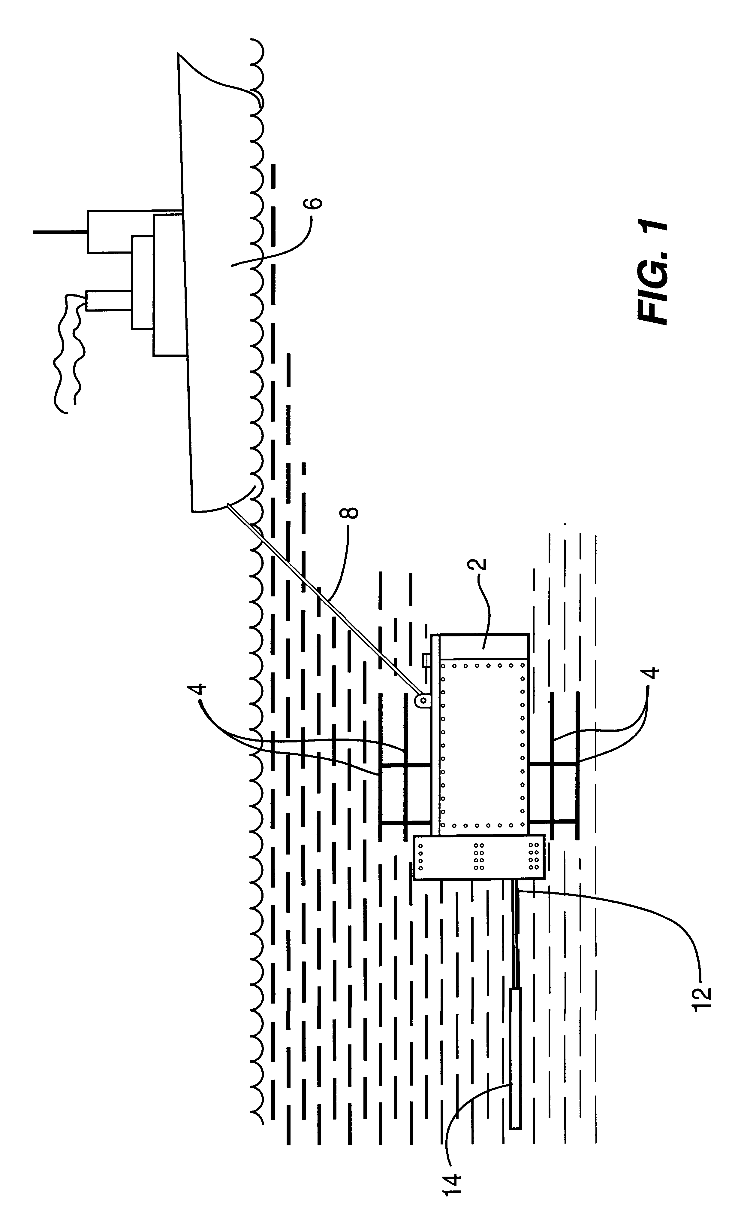
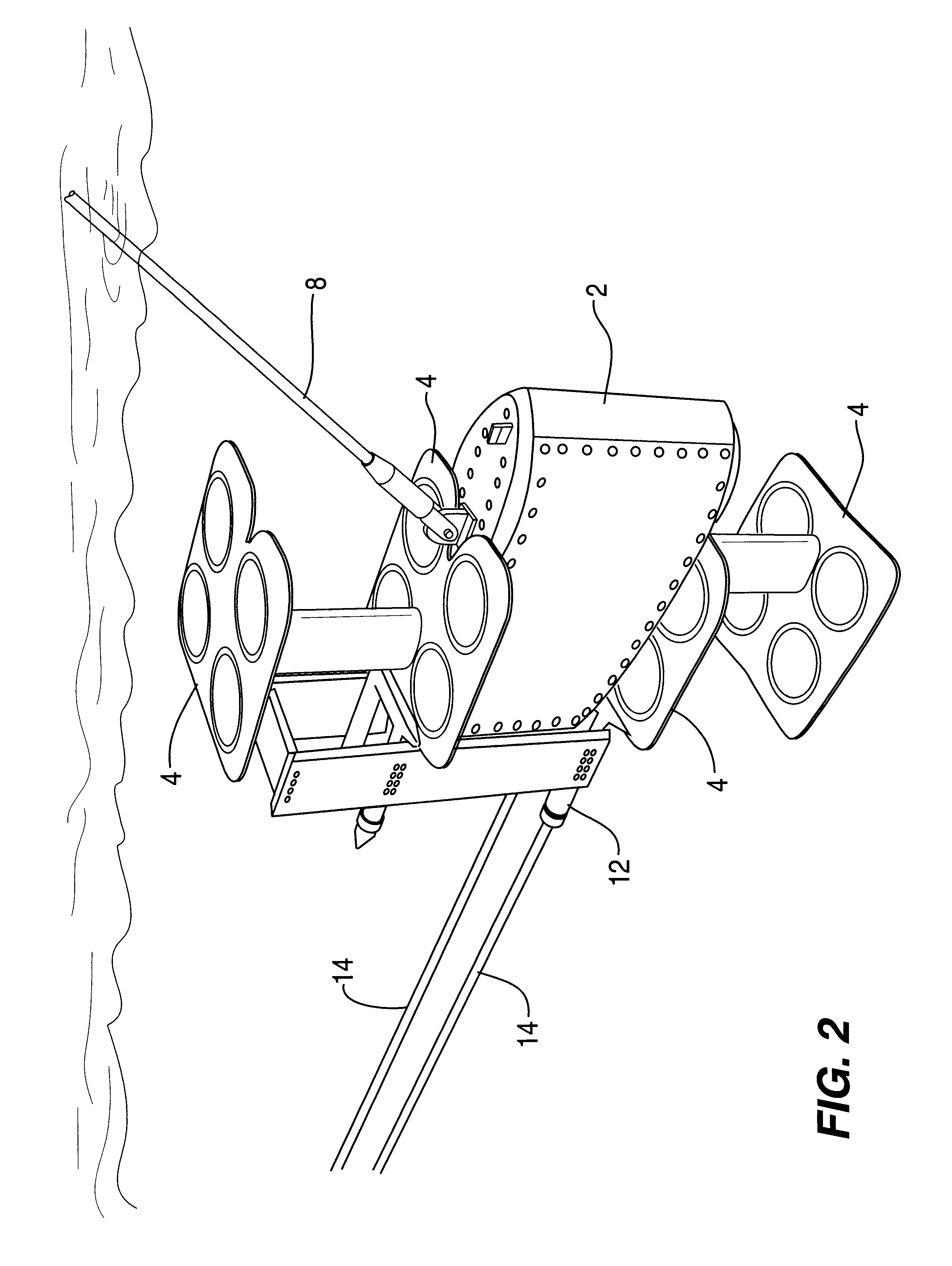
The tow body having acoustic projector and two receive arrays of 48 hydrophones each shown in FIG. 2 is deployed from a ship proceeding at a speed of 4 to 8 knots at an ocean location having a minimum depth of 600 meters. The cable scope is 300 meters to minimize reflections and ship noise. Transmit on one forward projector stave only. Transmission is at a level 3 dB below saturation measured at hydrophone No. 48 and No. 96, i.e. the closest hydrophones. All hydrophone data is decimated. The sample rate in this example is 512 samples per second.

Physical conditions of the projector and the arrays:

Forward Projector to first hydrophone distance is 7.85 ft.=8.35 dB spreading loss. Acoustic center of all projectors to forward hydrophone=7.49 ft.=7.9576 dB spreading loss.

Forward Projector to Aft Hydrophone distance=74.85 ft.=27.94 dB spreading loss. Total spreading loss from array end-to-end is 19.59 dB.

Distance to hydrophone No. 24 (mid array)=42.054 ft=22.93 dB. Spreading loss to Hydrop...


PUM


Abstract

The invention pertains to sonar receive arrays. More particularly, the invention pertains to a process for calibrating the amplitude, position and phase angle of an array of underwater receive hydrophones with respect to one another. The process requires projecting an acoustic test signal at a known frequency from a towed underwater acoustic projector toward an array of towed, underwater, interconnected, receive hydrophones; detecting and determining the response of the receive hydrophones to said test signal by signal processing means; and calibrating at least one parameter for the operation of the receive hydrophones resulting from the response. Calibrated parameters include the amplitude, position and phase angle of the receive hydrophones relative to one another.

Description

1. Field of the InventionThe invention pertains to sonar receive arrays. More particularly, the invention pertains to a process for calibrating the amplitude, position and phase angle of signals received from an array of underwater hydrophones with respect to one another. The array is linear and the hydrophones are distributed along the length thereof. Still more particularly, the invention pertains to the in situ measurement and calibration of various parameters which must be determined in order to calibrate and improve the performance of a towed array of receive hydrophones while the array is being towed through an underwater environment. The system operates by monitoring the responses of discrete hydrophones to generated acoustic test signals from a towed, stationary projector source.2. Description of the Related ArtThe gathering of data in an acoustic environment by means of an array of electrically interconnected hydrophones is important for commercial and military purposes. It...

Claims


Application Information

Patent Timeline
IPC IPC(8): G01H3/00G01V1/18G01V13/00G01V1/16G01V1/38
CPCG01H3/005G01V1/186G01V1/38G01V13/00
Inventor SKINNER, COLIN W.
Owner L 3 COMM CORP
Why Eureka
Try Eureka