Spreader attachment

Inactive Publication Date: 2001-04-03
GVM
View PDF15 Cites 52 Cited by
  • Summary
  • Abstract
  • Description
  • Claims
  • Application Information

AI Technical Summary

Problems solved by technology

While there have been many spreaders brought to the marketplace, the prior art spreaders do not produce a uniform distribution in a cost efficient manner.
Those spreaders that do effect a uniform distribution fail to spread over a sufficiently large enough area to keep the operation within reasonable costs.
While power take-off drives generally produce more constant circumferential speed, both powering methods

Method used


Image

  • Spreader attachment
  • Spreader attachment
  • Spreader attachment

Examples


Embodiment Construction

Whenever possible, the same reference numbers will be used throughout the figures to refer to the same parts.

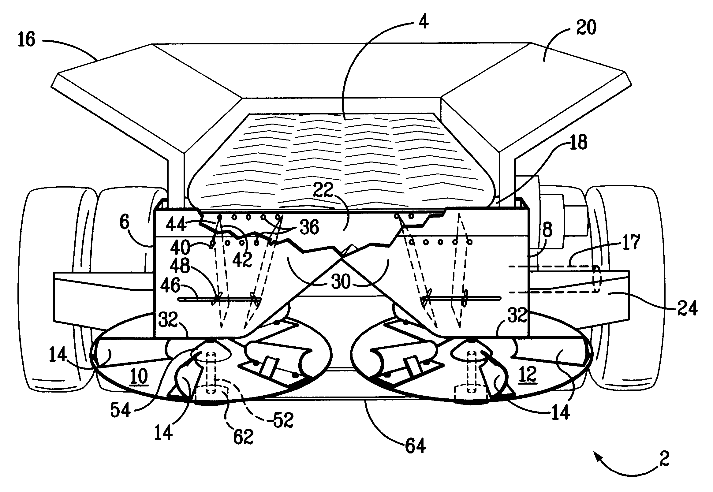
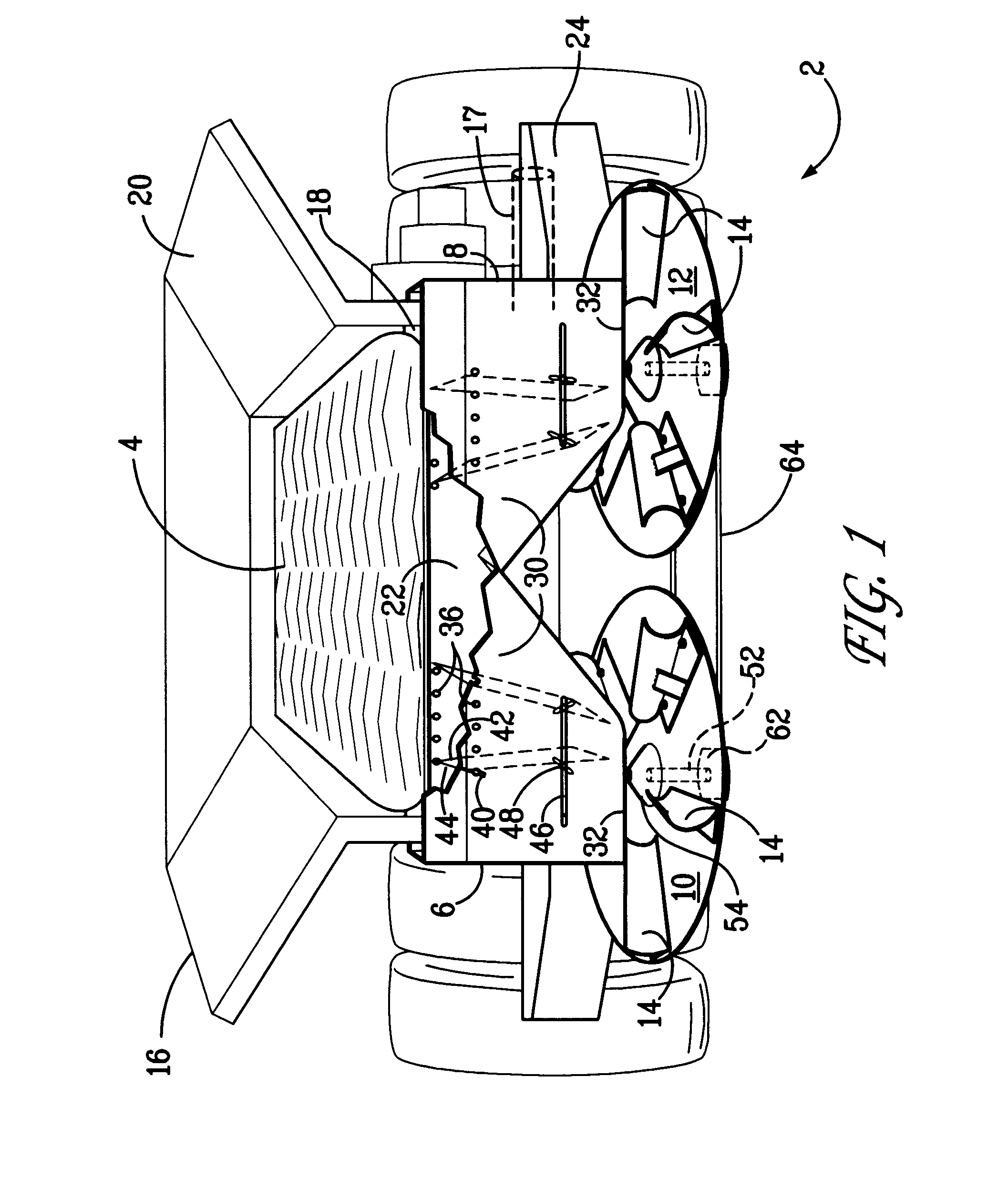
Referring now to FIG. 1 which shows the spreader attachment 2 of the present invention, the apparatus is comprised of a conveyor 4, first 6 and second 8 funnel units, and a first 10 and second 12 rotating disc, each having a plurality of blades 14 attached thereon. The apparatus of the present invention is mechanically attached, for example, by bolting or welding to the storage vehicle 16, such that the spreader attachment 2 of the present invention is cantilevered off the storage vehicle 16, and positioned below an exit orifice 18 of a hopper 20, the hopper 20 being attached to the storage vehicle frame.

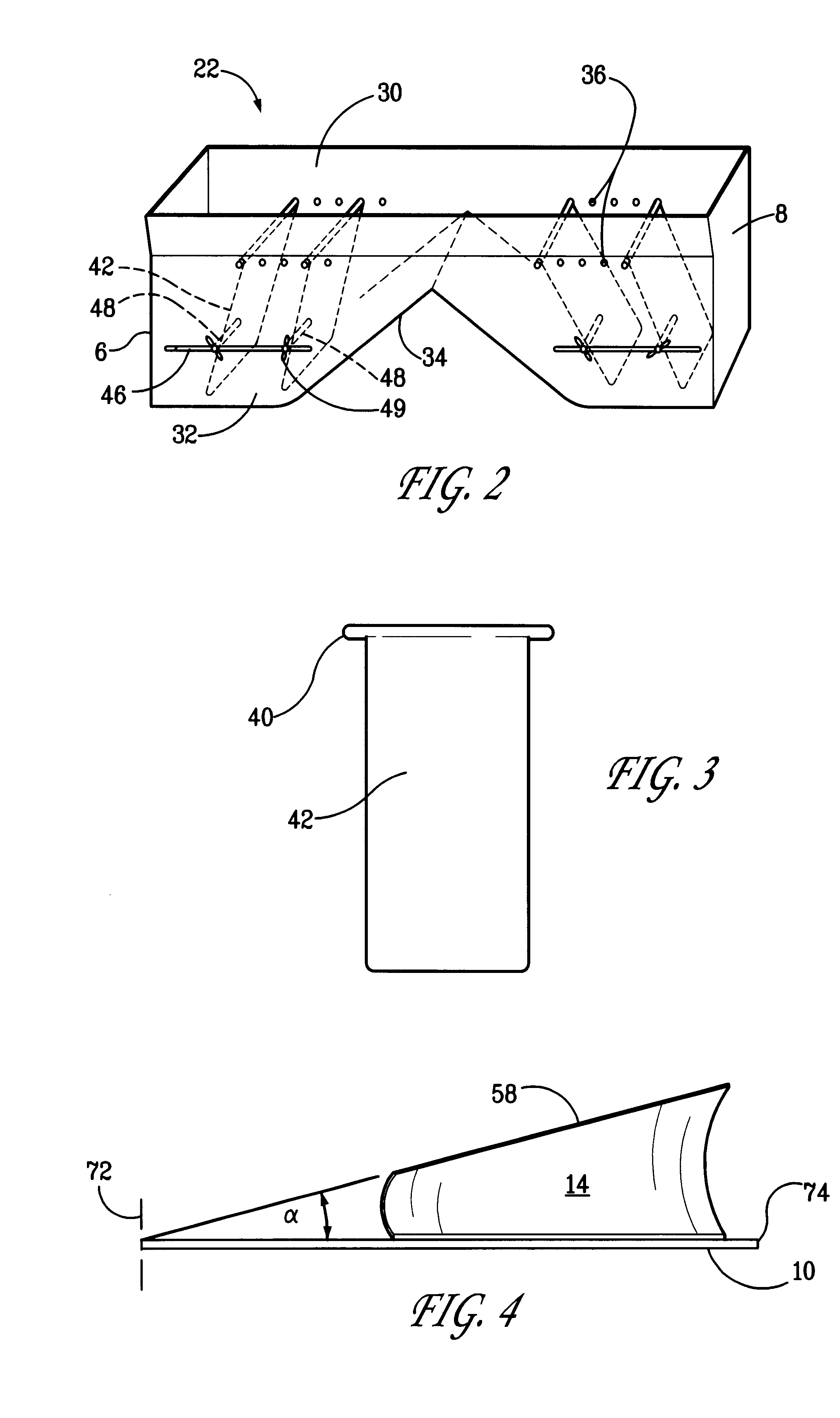
Positioned below the hopper exit orifice 18 so as to receive material exiting from the orifice 18 is a conveyor 4. The conveyor 4 is a rubber belt, but may be any transport method, for example, a screw type worm. The conveyor 4 terminates at a point above a drop box 22 compri...


PUM


Abstract

A dual disc spreader attachment utilizing a specific direction of disc rotation, pinpoint control of the impact point of material onto the disc and blade design to provide an optimal scatter pattern.

Description

1. Field of the InventionThis invention generally relates to a spreader attachment utilized to evenly distribute material, and specifically to a spreader attached to a farm vehicle to distribute granular and / or powdery material.2. Discussion of the Related ArtFarmers, landscapers, and others needing to spread material over large areas need a spreading device that will allow for rapid distribution of the material being spread, covering a large area in an even spread pattern, completed in a reasonably short period of time. The spreading device often determines the success of the operation. While there have been many spreaders brought to the marketplace, the prior art spreaders do not produce a uniform distribution in a cost efficient manner. Those spreaders that do effect a uniform distribution fail to spread over a sufficiently large enough area to keep the operation within reasonable costs.Dual disc centrifugal spreaders are well known in the art. They generally are comprised of fla...

Claims


Application Information

Patent Timeline
IPC IPC(8): A01C17/00
CPCA01C17/006
Inventor ANDERSON, MARK W.
Owner GVM
Why Eureka
Try Eureka