
Method and apparatus for measuring the state-of-charge of a battery

Inactive Publication Date: 2001-04-03
FORD GLOBAL TECH LLC
View PDF9 Cites 47 Cited by
  • Summary
  • Abstract
  • Description
  • Claims
  • Application Information

AI Technical Summary

Benefits of technology

to provide a method and an apparatus for accurately measuring the state-of-charge of a battery and which overcomes some or all of the previously delineated drawbacks associated with prior battery state-of-charge measuring devices.
According to a second aspect of the present invention an apparatus for use in combination with a battery having an electrical charge is provided. The apparatus includes a first portion which is selectively coupled to the battery for a first period of time and which measures the electrical charge of the battery during the first period of time; a second portion which is selectively coupled to the battery for a second period of time and which measures the electrical charge of the battery during the second period of time; and a third portion which is selectively coupled to the first portion during the second period of time and to the second portion during the first period of time and which calibrates the first portion during the second portion of time and which calibrates the second portion during said first period of time, thereby allowing the first portion and the second portion to cooperatively provide an accurate measurement of the amount of charge of said battery.

Problems solved by technology

While these state-of-charge measuring devices do effectively maintain and display the state-of-charge of a battery, they suffer from some drawbacks which undesirably reduce their respective accuracy.
Thus, this "unmeasured electrical current" is not factored into the "running total" kept by these devices, thereby causing these devices to produce inaccurate and / or erroneous "state-of-charge" estimates.
While these extrapolation techniques have been shown to somewhat reduce the overall error, they are not highly accurate and often result in the creation of relatively small errors which accumulate over time, causing the creation of relatively large undesirable state-of-charge measurement errors.
These techniques further add undesirable complexity to these prior state-of-charge devices.
Additionally, the capacitance values of these capacitors often drift or vary over time.
Any uncompensated variance in these capacitance values will cause these prior devices to further provide inaccurate state-of-charge measurements.
However, while these devices are being calibrated, no measurement is made of the electrical current flowing into and out of the battery, thereby further increasing the state-of-charge measurement error.

Method used


Image

  • Method and apparatus for measuring the state-of-charge of a battery
  • Method and apparatus for measuring the state-of-charge of a battery
  • Method and apparatus for measuring the state-of-charge of a battery

Examples


Embodiment Construction

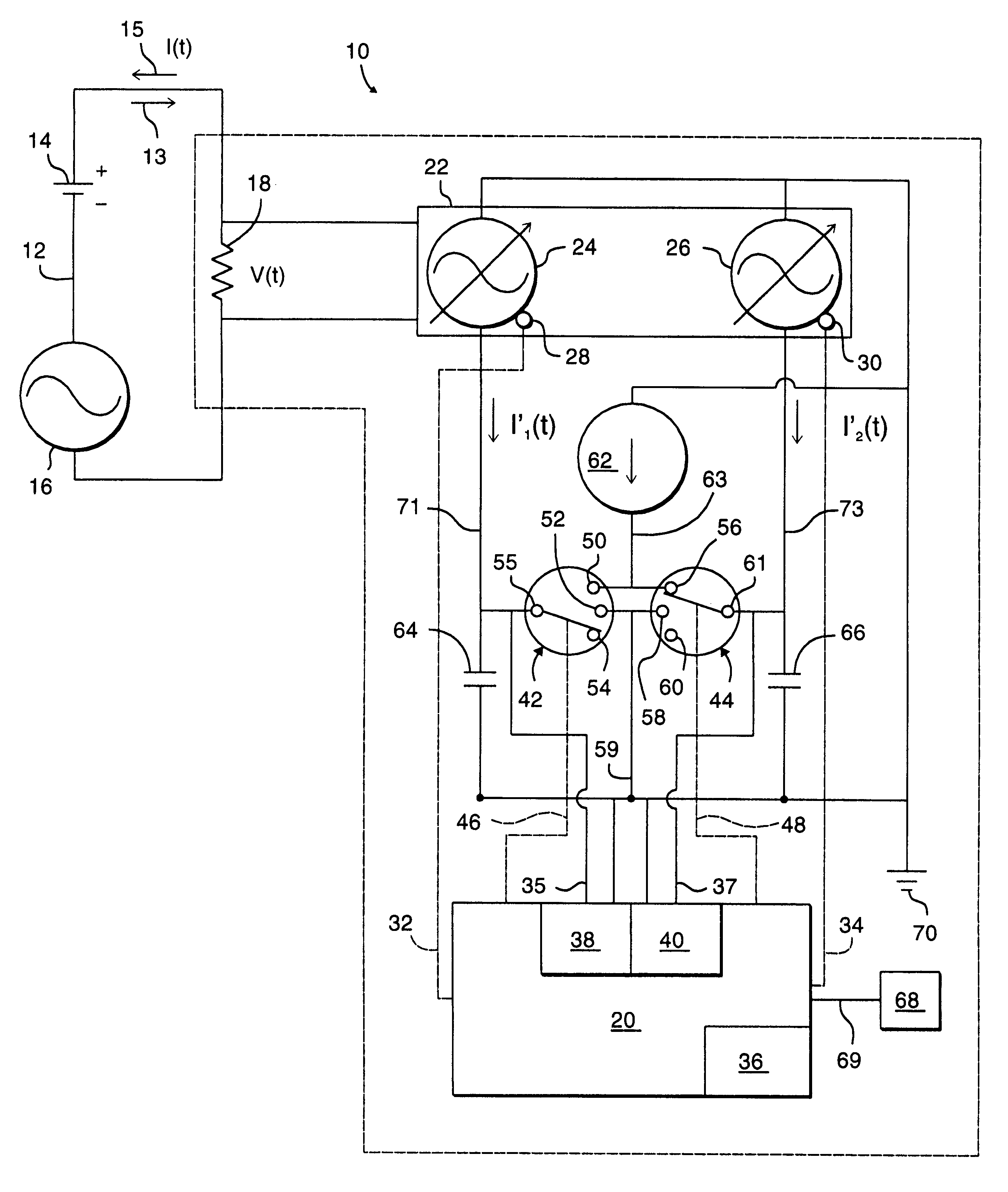
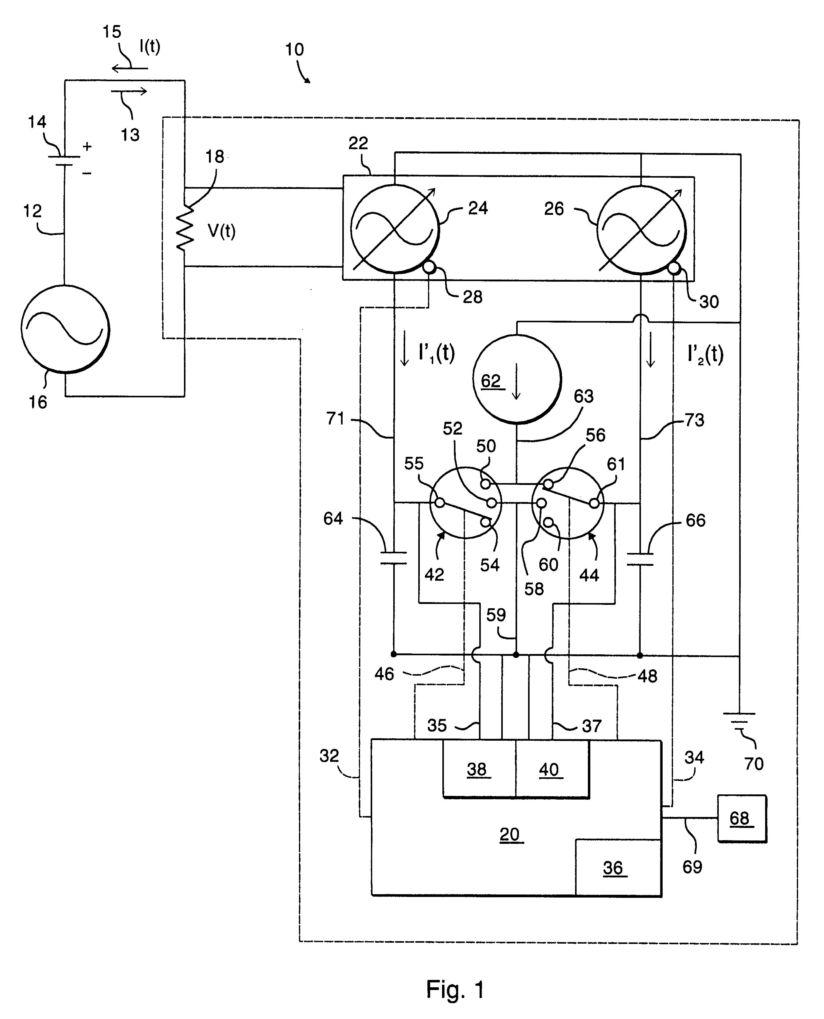
Referring now to FIG. 1, there is shown an apparatus 10 for measuring the state-of-charge of a battery and which is made in accordance with the teachings of the preferred embodiment of the invention. Particularly, apparatus 10 is connected in "electrical series" with a conventional and / or typical storage cell or battery 14 and to a variable current load 16. Battery 14, variable current load 16 and apparatus 10 therefore, as shown cooperatively form an "electrical series type" circuit 12.

In the preferred embodiment of the invention, variable load 16 includes and functionally represents both electrical discharging / depleting components (e.g., components which remove electrical current or electrical charge from battery 14), such as an electric motor, electric lights, and / or heating elements, as well as electrical recharging / supplying components (e.g., components which replace or transfer electrical current or electrical charge into battery 14), such as an alternator and / or battery charg...


PUM


Abstract

An apparatus 10 for measuring the state-of-charge of a battery 14. Apparatus 10 includes a shunt resistor 18, a pair of capacitors 64, 66, and a controller 20. Controller 20 selectively and alternatively measures the electrical charge of battery 14 with a first of capacitors 64, 66 while selectively discharging and calibrating the other capacitor 64, 66. In this manner, controller 20 continuously provides an accurate measurement of the "state-of-charge" of battery 14.

Description

(1). FIELD OF THE INVENTIONThis invention relates to a method and to an apparatus for measuring the state-of-charge of a battery and more particularly, to a method and to an apparatus for accurately measuring the state-of-charge of a vehicle battery.(2). BACKGROUND OF THE INVENTIONBatteries are used in many assemblies, such as in vehicles, to provide electrical power to the various components and / or devices which cooperatively and respectively form these assemblies. It is highly desirable to accurately and continually measure and / or ascertain the electrical charge remaining within the battery, commonly referred to as the "state-of-charge", in order to ensure that the battery is timely and efficiently recharged or replaced, and to further ensure continued and substantially uninterrupted operation of the vehicle or other type of "battery powered" assembly. Consequently, many devices have been developed and have been used to selectively measure the state-of-charge of a battery and to s...

Claims


Application Information

Patent Timeline
IPC IPC(8): G01R31/36G01R31/00
CPCG01R31/361G01R31/3648G01R31/006G01R31/3828
Inventor STASKO, JOHN CHRYSOSTOM
Owner FORD GLOBAL TECH LLC
Features
  • Generate Ideas
  • Intellectual Property
  • Life Sciences
  • Materials
  • Tech Scout
  • Unparalleled Data Quality
  • Higher Quality Content
  • 60% Fewer Hallucinations
Learn More