Non-contact system for detecting an angle of rotation

a technology of non-contact system and angle of rotation, which is applied in the direction of mechanical measurement arrangement, instruments, machines/engines, etc., can solve the problems of large temperature dependency and pressure dependency, large angular range of 180.degree. can be detected unambiguously, and the angular range is too small for detecting the position of the camsha

Inactive Publication Date: 2001-04-10
ROBERT BOSCH GMBH
View PDF32 Cites 76 Cited by
  • Summary
  • Abstract
  • Description
  • Claims
  • Application Information

AI Technical Summary

Benefits of technology

will now be illustrated in more detail with the aid of the following

Problems solved by technology

This could have disadvantages, because Hall sensors, for instance, have great temperature dependency and great pressure dependency.
Magnetoresistive sensor elements, conversely, have better properties with regard to temperature and pressure dependency, being less temperature- and pressure-dependent than Hall sensors, but have the disadvantage that because of the physical effect, only an angular range of 180.degree. can be detected unambiguously.
Such an angular range is too small for detecting the position of the camshaft of an internal combustion engine.

Method used


Image

  • Non-contact system for detecting an angle of rotation
  • Non-contact system for detecting an angle of rotation
  • Non-contact system for detecting an angle of rotation

Examples


Embodiment Construction

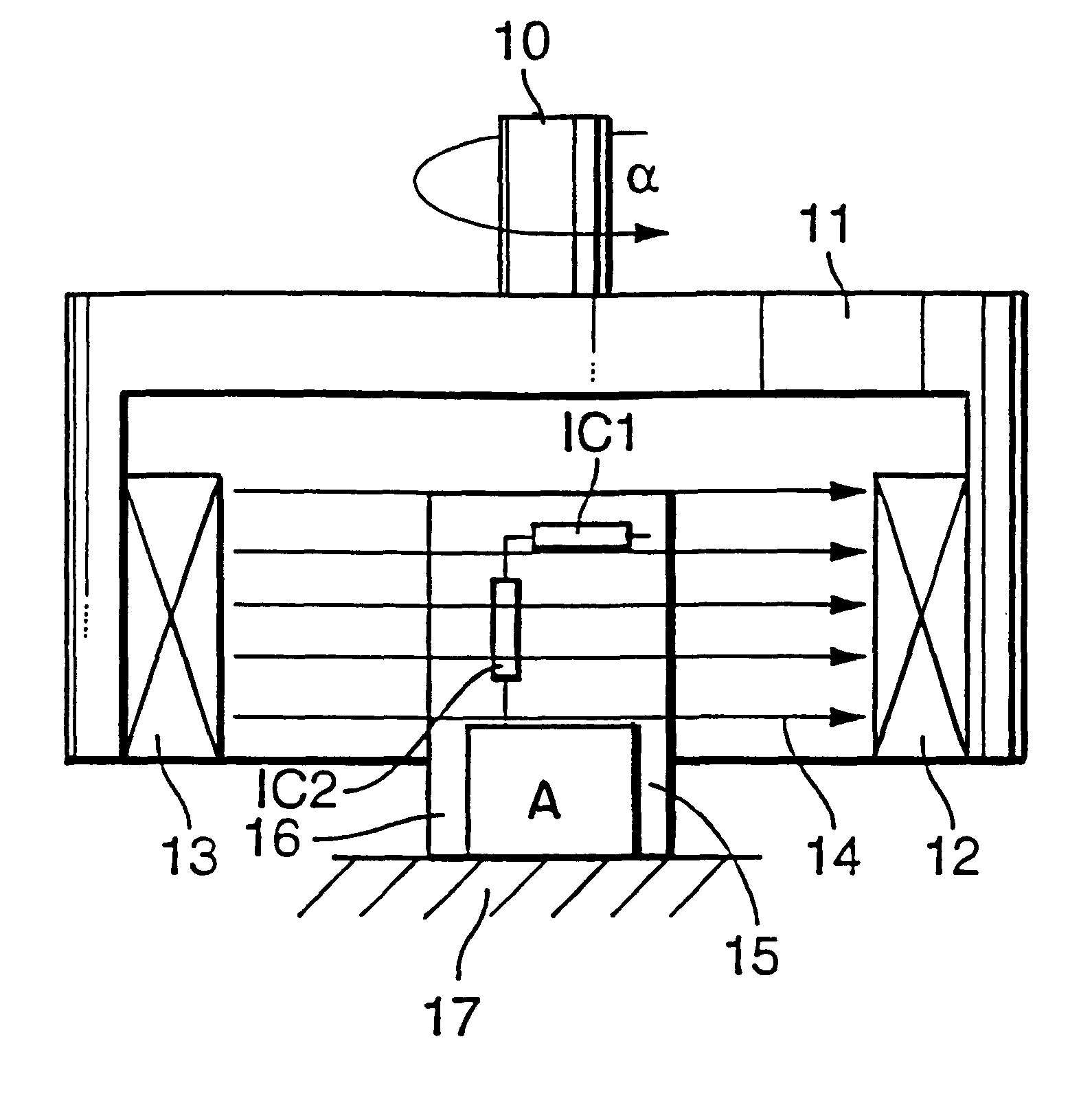
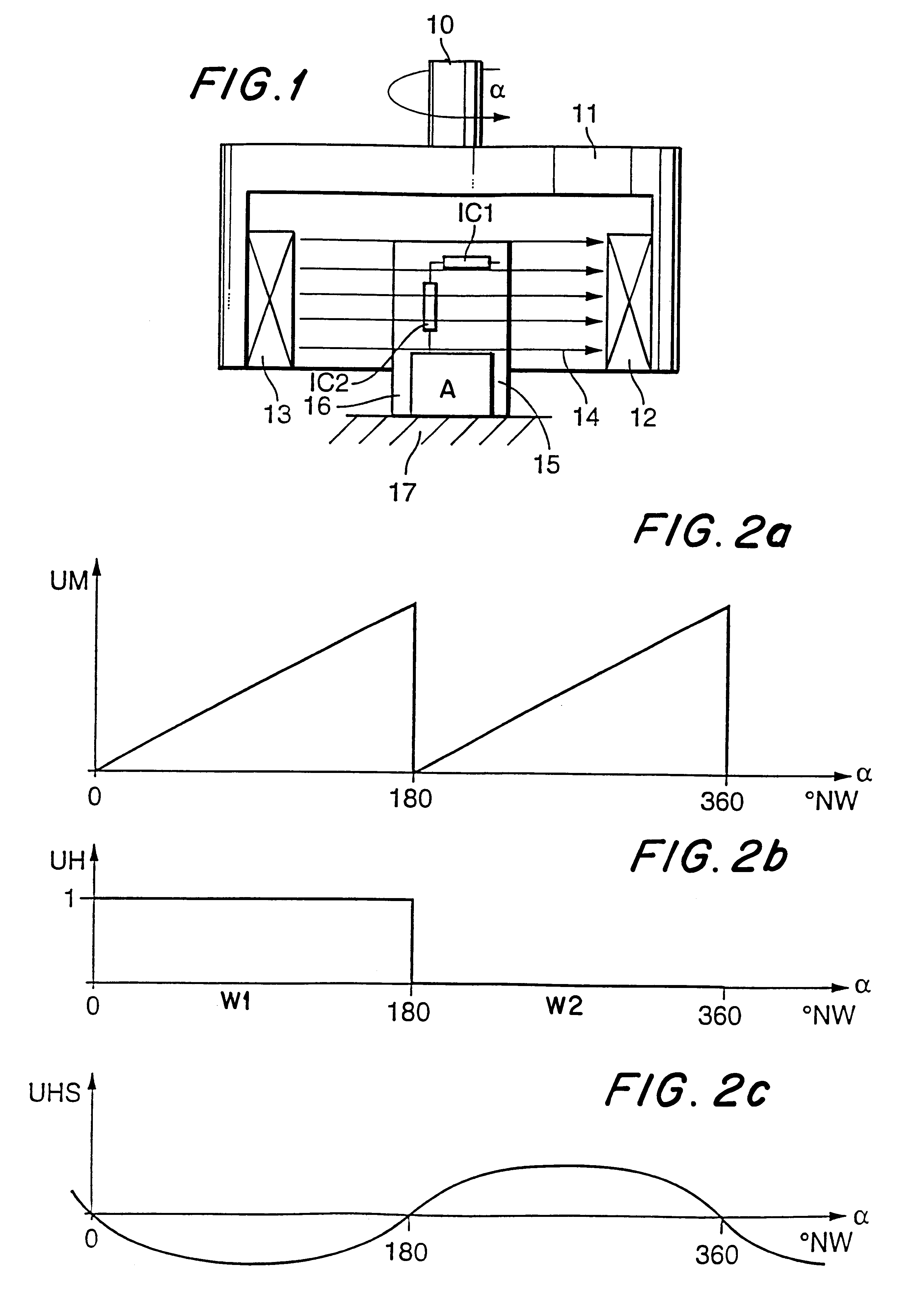
In FIG. 1, an exemplary embodiment of the arrangement according to the invention is shown. The intent is to ascertain the angular position of the rotatable shaft 10, for instance the camshaft of an internal combustion engine. Connected to the shaft 10 is a disk 11, which for instance is cylindrical and which has two magnets 12, 13, or one magnet whose poles are magnetically coupled via the disk, and whose polarity or disposition is such that an approximately homogeneous magnetic field 14 develops between the magnets. This magnetic field rotates with the shaft 10.

The magnetic field sensitive portion of the magnetic field sensor 15 includes the two sensor elements IC1 and IC2, which are located on a substrate 16. The magnetic field sensor 15 is held by means of a sensor mount 17.

The sensor element IC1 includes a sensitive element which operates by utilizing the magnetoresistive effect to ascertain the angle between the magnetic field and the of rotation sensor. Since because of the ph...


PUM


Abstract

The arrangement for contactless determination of an angular position of a rotatable element, such as a camshaft of an internal combustion engine, which includes a magnet arranged to rotate with the rotatable element; a magnetic field sensor stationary in relation to the rotatable element and including a first sensor element (IC1) and a second sensor element (IC2), wherein the first sensor element generates a first output signal linearly dependent on an angle between the magnetic field and the magnetic field sensor according to a magnetoresistive effect, whereby the first output signal has respective values between 0° and 180° that repeat between 180° and 360°, and the second sensor element generates a second output signal having a high value between 0° and 180° and a low value between 180° and 360° according to a Hall effect; and an evaluation circuit (A) for analyzing output signals of both sensor elements to determine the angular position of the rotatable element between 0° and 360°. The evaluating circuit finds that the absolute angular position is either of two angular orientations spaced 180° from each other only from the signal from the first sensor element and selects one of them as the absolute angular position according to the second output signal.

Description

1. Field of the InventionThe invention relates to an arrangement for the contactless determination of an angle of rotation of a rotatable element, in particular a shaft of an internal combustion engine, in which, comprising means for generating a magnetic field rotating with the rotatable element, a magnetic field sensor for detection of magnetic field intensity and an evaluation circuit for determining the angular orientation or position of the rotatable element from the magnetic field sensor output signals.2. Prior ArtArrangements of this kind, with which a determination of an angle of rotation can be performed, are known for instance from Published, Non-Examined German Patent Application DE-OS 195 43 562. In these arrangements, a magnet is connected to the rotatable shaft whose angular position is to be ascertained. The magnetic field, which varies with the angle of rotation of the shaft, is measured with the aid of two sensor elements. These sensor elements are either two Hall s...

Claims


Application Information

Patent Timeline
Patent Type & Authority Patents(United States)
IPC IPC(8): F02P7/07F02P7/00F02P7/067G01D5/12G01B7/30G01D5/14G01D5/16G01B7/00
CPCF02P7/067F02P7/07G01B7/30G01D5/145
Inventor OTT, KARLLEHNER, MICHAEL
Owner ROBERT BOSCH GMBH
Why Eureka
Try Eureka