Frame with environment resistant members

a technology of environment-resistant members and frames, which is applied in the direction of frames, joists, windows/door frames, etc., can solve the problems of affecting the cell structure of treated lumber, the relative distortion of historical treated lumber, and the less desirable treatment of treated lumber, so as to minimize the present warping, the effect of cost saving and cost saving

Inactive Publication Date: 2001-04-17
BARNETT PAUL
View PDF4 Cites 8 Cited by
  • Summary
  • Abstract
  • Description
  • Claims
  • Application Information

AI Technical Summary

Benefits of technology

One purpose of the present invention is to provide for a combination of low warping with treatment technologies along with untreated or very low warping treatment technologies in order to provide a wood product which has as inexpensive a cost as possible while utilizing wood and wood glues without composites and more particularly without composite at the point where the joining occurs.
The technology also allows for the use treated lumber along with composite materials for purposes which will be better understood from a reading of the entire description which describes where composites are used to further minimize the warping present with treated lumber.
It should be noted that the present technology can be used with integrated composite products so that untreated wood, treated wood and composites are all used consistently.
This might be desirable where more control is desired over the treated wood in order to prevent warping or where a smaller amount of composite material is desired in order to save cost but where a longer area of treatment is believed necessary then the area treated with composite.
In addition, the process for making the present invention a significantly less expensive than the process for using composites since all of the steps associated with the milling of composites are eliminated since only wooden are utilized in the present invention.

Problems solved by technology

Historically treated lumber grossly distorted relative to untreated lumber.
This is because the cell structure of the treated lumber is affected by the method of treatment.
Historically for finish work and door jams and window jams and related products treated lumber has been less desirable because even a fairly small length of treated lumber will warp disproportionately.

Method used


Image

  • Frame with environment resistant members
  • Frame with environment resistant members
  • Frame with environment resistant members

Examples


Embodiment Construction

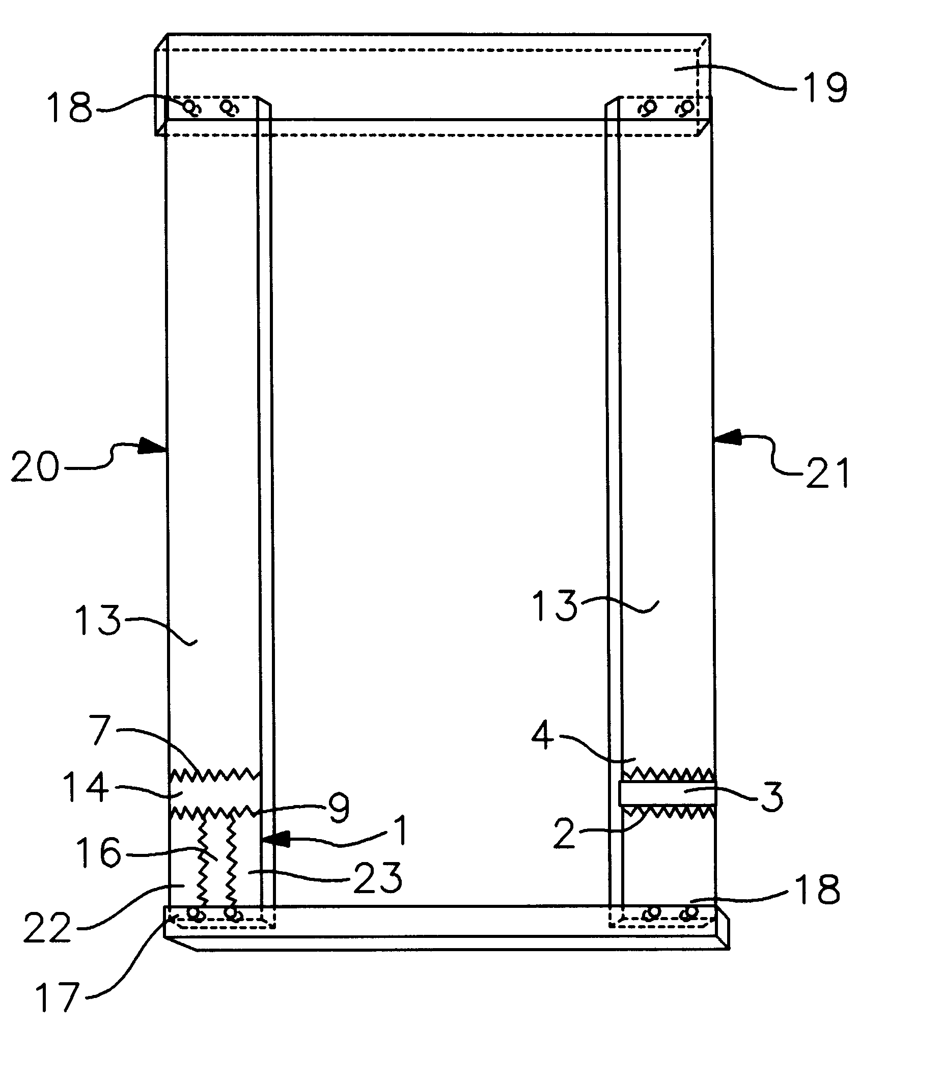
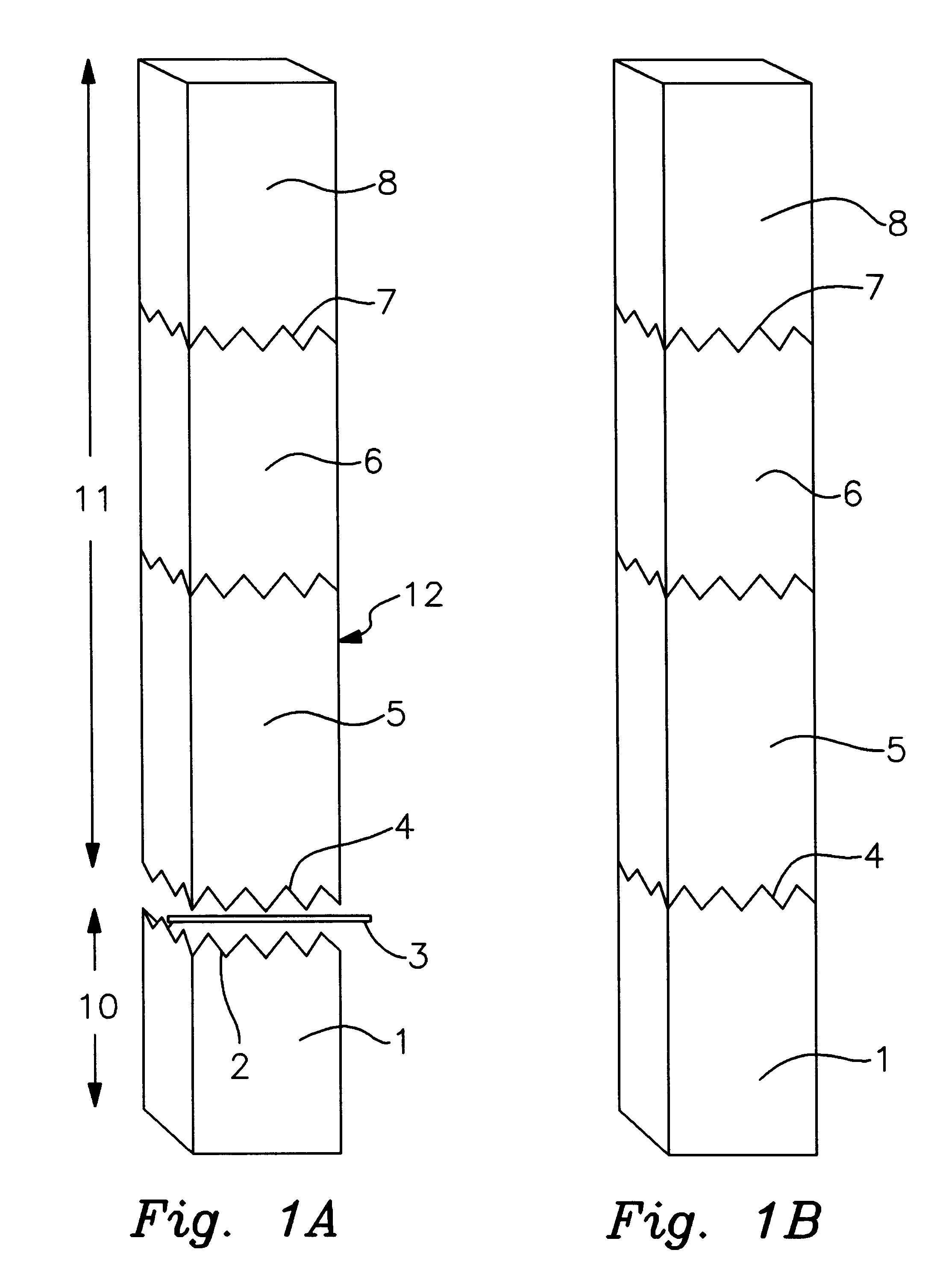
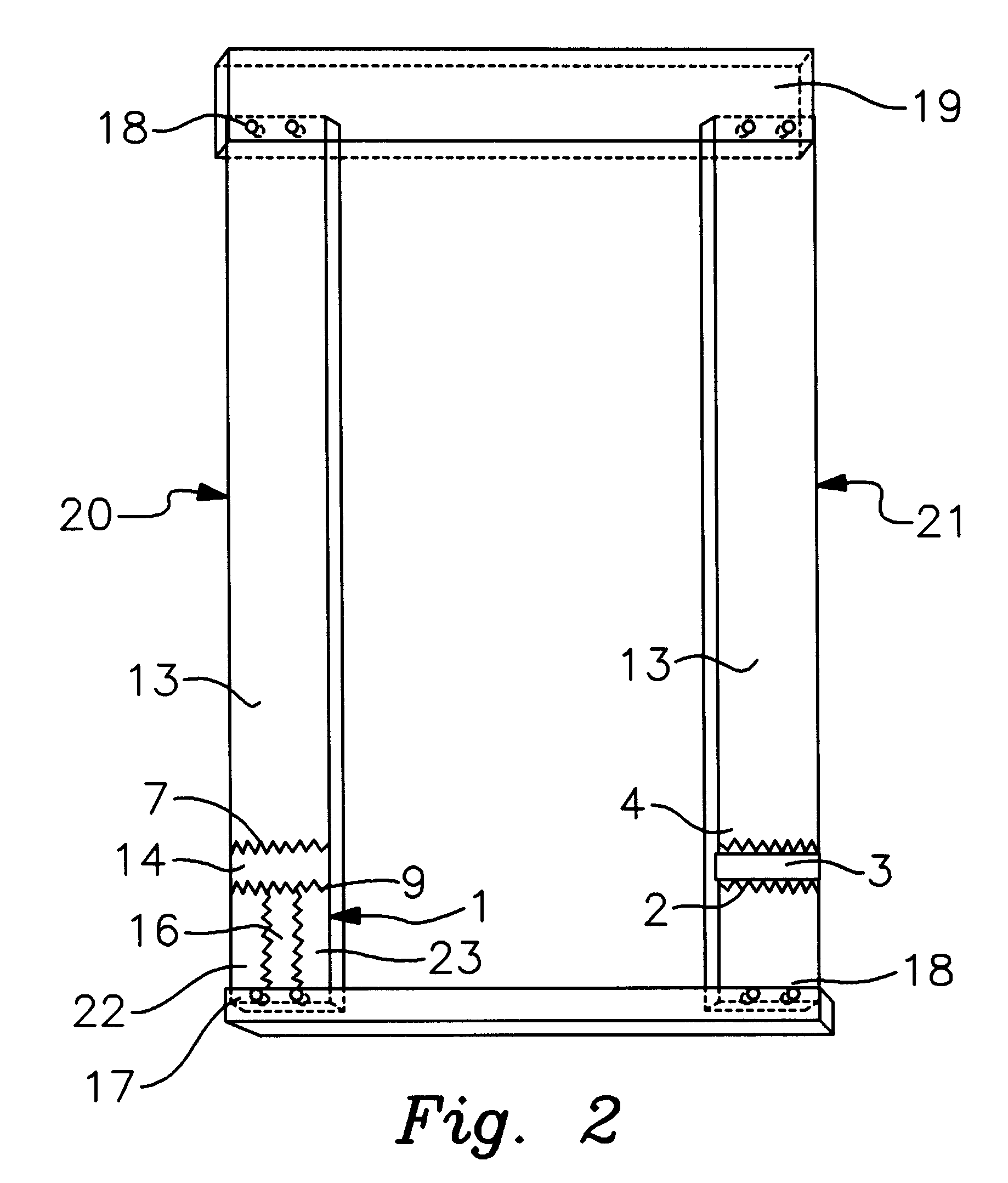
As can best be seen by FIG. 1a the invention comprises a first lumber member 1 (which may itself be made of several different lengths of lumber joined) having a serrated edge 2 which is joined by glue 3 to a corresponding serrated edge 4 of a second lumber member 5 in order to form a continuous unit. The glue line made of glue 3 is shown in an exaggerated size for reference purposes only. The quantity of size of the glue line formed by the glue is governed by the amount of glue desired for this type of joining process and is typically a very thin line, most of the glue being forced out of the interface of the corresponding serrated edges by the hydraulic press which pushes the first lumber member 1 into the second lumber member 5. FIG. 1b shows the joined edge 9 of the members 1 and 5. First lumber member is a KDAT treated or otherwise treated member which has a length defined by the parameters of the ultimate use and quality control standards requiring the treated first lumber memb...


PUM


Abstract

A frame for improved moisture, decay and insect resistance includes frame members each possessing a short treated lumber member joined to a longer untreated lumber member so that the length of the overall board achieves a desired length with an acceptable amount of distortion. The untreated member may be treated but the treatment is not so invasive as to impart a high degree of warping. The treated member may have more or less treatment depending on the amount of distortion which is acceptable. Top and bottom boards connect the frame members to form a door frame.

Description

BACKGROUND OF INVENTION1. Field of InventionThe invention relates to framing members. More specifically, the invention relates to framing members which have an environment resistant portion and a less resistant portion.2. Prior ArtThe closest prior art to the present is U.S. Pat. No. 5,661,943 issued to Hagle in 1997. The Hagle patent uses a composite material to provide weather resistance along the bottom of a frame.This particular technology represents a combination of composite materials with non-composite timbers. This particular combination is well known in the prior art in various settings. The prior art envisions the use, for example, of a relatively expensive composite wood product joined to an inexpensive wood product where only the expensive wood product is to be exposed for view. One example is where carpeted steps have a exposed wooden portion. Under those circumstances an inexpensive type of timber, such as pine is joined to a more expensive end piece, such as oak so th...

Claims


Application Information

Patent Timeline
Patent Type & Authority Patents(United States)
IPC IPC(8): E06B1/04E06B1/06E04C3/12E04F19/00
CPCE04C3/12E06B1/06E04F19/00
Inventor BARNETT, PAUL
Owner BARNETT PAUL
Why Eureka
Try Eureka