
Sterilization container

a container and container technology, applied in the field of sterilization containers, can solve the problems of increasing the cost and time it takes to assemble the container, not providing enough open space within the container to allow, and increasing the cost and time it takes to sterilize the container

Inactive Publication Date: 2001-04-17
SYMMETRY MEDICAL MFG INC
View PDF25 Cites 215 Cited by
  • Summary
  • Abstract
  • Description
  • Claims
  • Application Information

AI Technical Summary

Benefits of technology

Another object of the invention is to provide a container of this type which enhances the sterilization process so that sterilization can be carried out in a minimum amount of time.
A further object of the invention is to provide a sterilization container which prevents the accumulation of moisture within the container.
A further object of the invention is to provide a container of this type which promotes the circulation of steam within the container during the sterilization process.
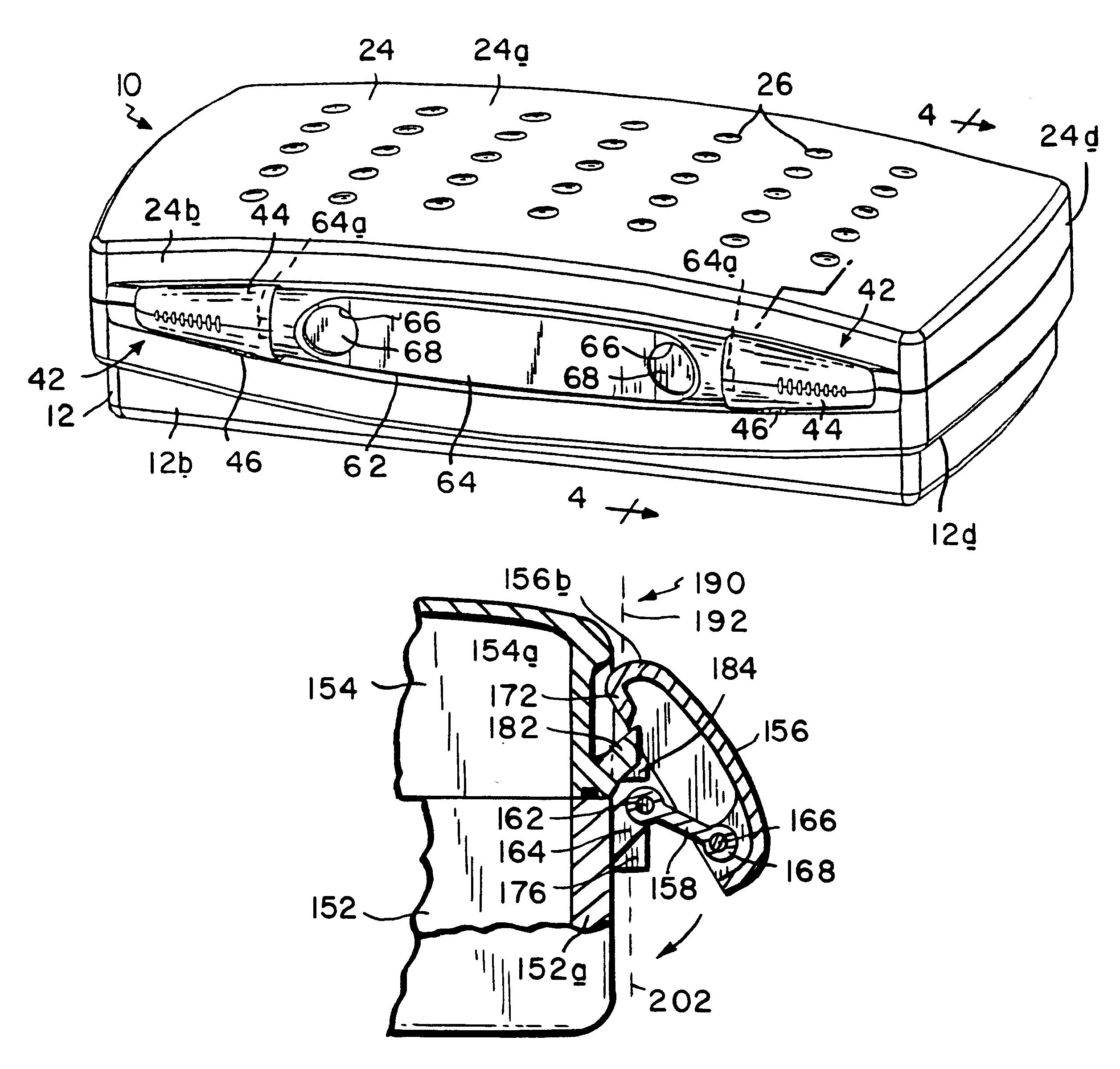
Preferably, the container is provided with at least one latch which can latch the cover in its closed position and a safety lock releasably attached to the receptacle and cover for preventing each latch from being unlatched without providing a visual indication that such unlatching has occurred. Thus, medical personnel can take an already sterilized container off the shelf and, by observing the safety lock, determine that the container has been opened after sterilization such that the contents of the container are no longer in a sterile condition.
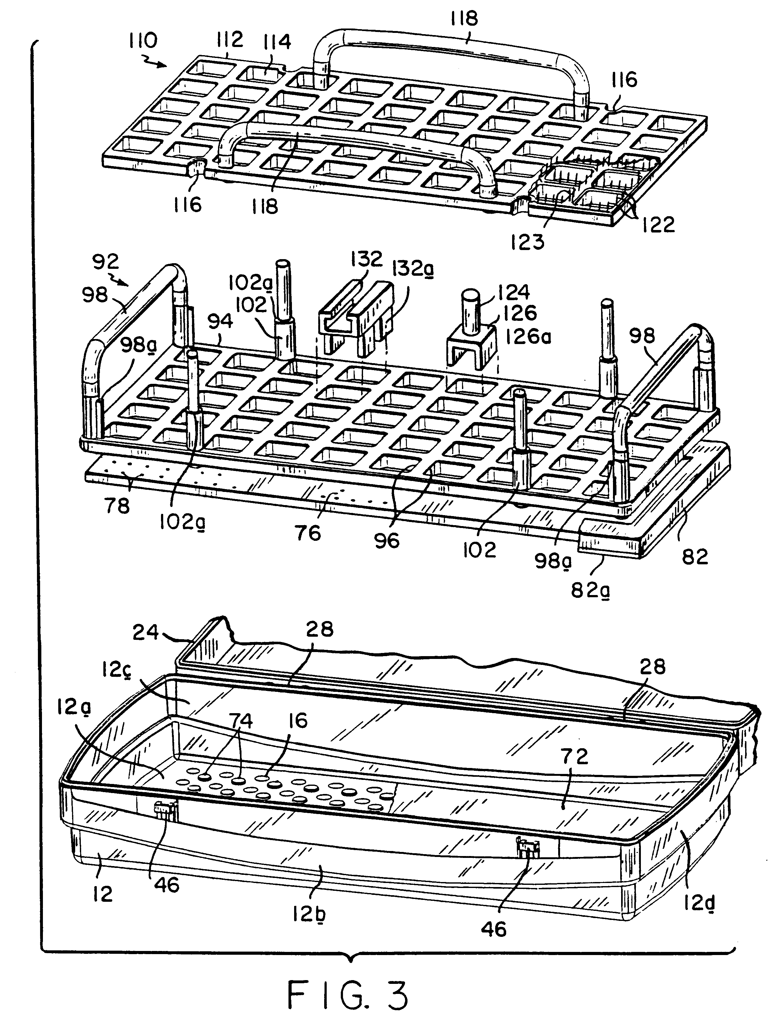
Further as will be described, the interior components of the container are designed to promote efficient and thorough circulation of steam within the container during sterilization and to facilitate proper presentation of instruments that were sterilized in the container when it is time to use those instruments. Specifically, during sterilization, the thermally conductive plate functions as a heat source which re-vaporizes condensate dropping into the plate from the trays and instruments thereon thereby enhancing the sterilization process and preventing the condensate from wetting the filter sheet.

Problems solved by technology

Some do not provide enough open space within the container to allow steam to penetrate, and circulate within, the container.
Therefore, the sterilization cycle for such containers is relatively long, particularly if the sterilizer or autoclave does not include a vacuum cycle wherein air is drawn from the container prior to the injection of steam into the container.
However, this solution requires the placement in the container of a corresponding number of filter sheets which increases cost and the time it takes to assemble the container.
However, they are heavy and expensive and the heat-sterilized container cannot be handled until after it is cooled off which effectively increases the length of the sterilization cycle.
However, those containers are not entirely satisfactory because it has been found that moisture accumulates within the container which moisture tends to wet the filter sheet thereby degrading its effectiveness as a microbial filter.
In other such containers, the filter sheet is not sufficiently protected from medical instruments and other components within the container with the result that the sheet is penetrated, again destroying its effectiveness as a filter.
Still further, some prior containers of this general type are not designed to facilitate loading the container with medical instruments in a given order before sterilization so that those instruments will remain in the same position during sterilization and subsequent handling so that when it is time to use the instruments, they can be presented to a surgeon in a desired order for a particular procedure.
Finally, with prior sterilization containers of this general type, one cannot be assured that a sterilized container has remained unopened such that the instruments in the container are still in a sterile condition when it is time to use the instruments.

Method used


Image

  • Sterilization container
  • Sterilization container
  • Sterilization container

Examples


Embodiment Construction

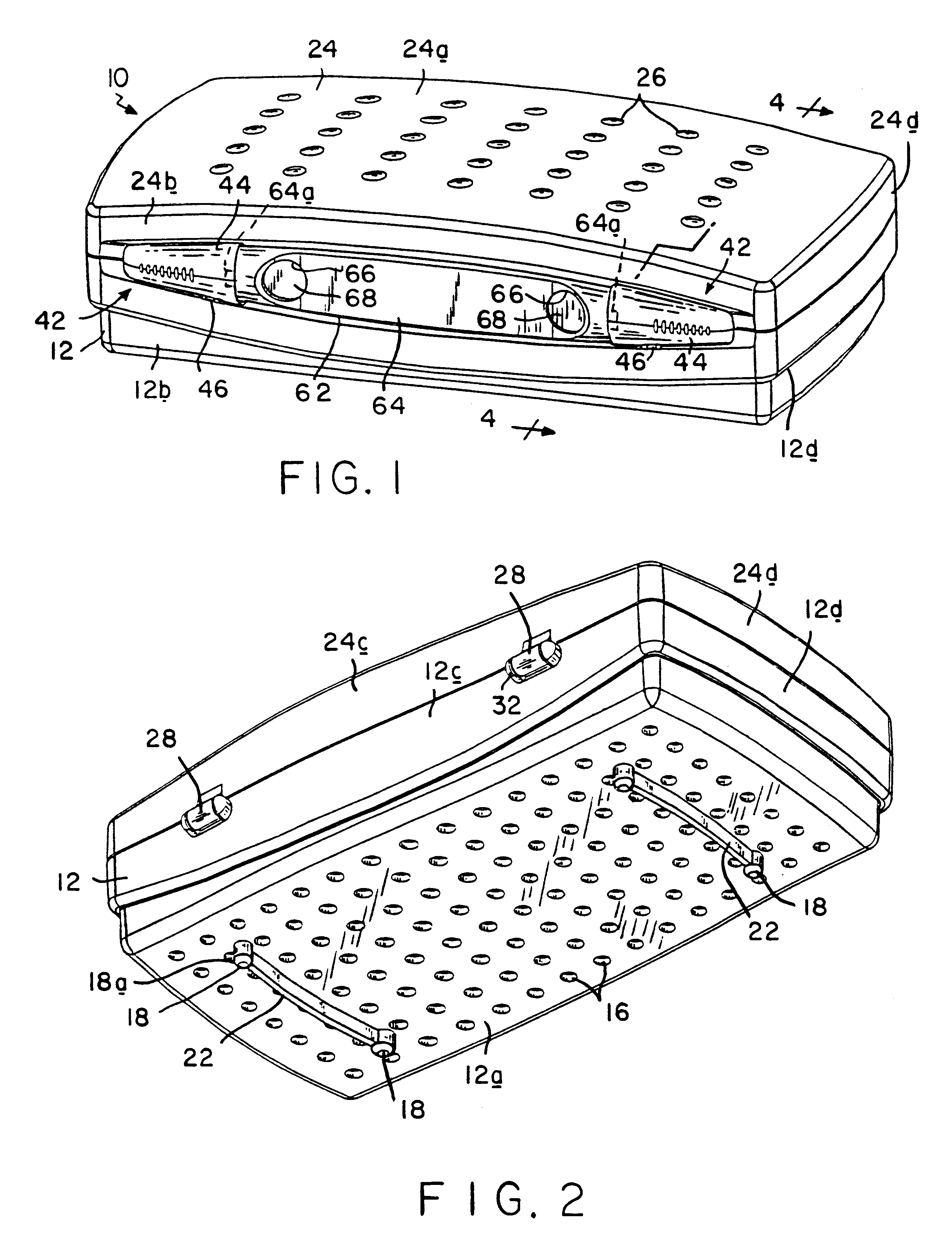
Referring to FIGS. 1 and 2 of the drawings, our container comprises a housing indicated generally at 10 made of a rugged, impact resistant, medical grade; transparent plastic material. The housing is composed of a generally rectangular receptacle 12 having a bottom wall 12a, a front wall 12b, a rear wall 12c and a pair of mirror-image end walls 12d all extending up from the bottom wall 12a to form an open top box-like structure. As beset seen in FIG. 2, an array of vent openings 16, each being about 3 / 5in. in diameter, is provided in bottom wall 12a, these openings being distributed in columns and rows over substantially the entire area of the bottom wall. Also, pairs of front and rear legs 18 extend down from the bottom wall adjacent opposite ends of receptacle 12, each pair of legs being connected by a depending rib 22 which is specially curved as will be described in more detail later.

Housing 10 is provided with a rectilinear cover 24 which is shaped and arranged to close the ope...


PUM

PropertyMeasurementUnit
temperatureaaaaaaaaaa
pressureaaaaaaaaaa
fine structureaaaaaaaaaa

Abstract

A sterilization container for medical instruments includes a receptacle with a bottom wall and an open top, there being a multiplicity of vent openings in the bottom wall. The receptacle has a cover movable between a closed position wherein the cover closes the open top of the receptacle and an open position wherein the cover is positioned to allow access to the interior of the receptacle. A filter sheet is positioned in the receptacle so as to cover the bottom wall and the vent openings therein and the receptacle contains one or more trays for supporting medical instruments above the filter sheet. A perforated highly thermally conductive plate is positioned between the trays and the filter sheet so that when steam enters the container through the vent openings during steam sterilization, it heats the plate to a temperature sufficient to revaporize steam condensate collecting on the plate. The internal structure of the container is also disclosed.

Description

1. Field of the InventionThis invention relates to a sterilization container. It relates more particularly to a container for medical instruments and other articles which are to be sterilized by exposure to steam.Prior to their use, medical and surgical instruments have to be sterilized. This is often done by placing the instruments in a container and inserting the container into an autoclave where the container and its contents are subjected to high temperature steam under pressure. The container is designed to allow steam to enter the container during the sterilization process so that the steam contacts the instruments therein. In some cases, the container is equipped with a valve which opens under the pressure of the steam in the autoclave and which closes following the sterilization process so that the container remains sealed until it is time to use the instruments. Other sterilization containers have permanent vent openings which are covered by a microbial filter. The filter a...

Claims


Application Information

Patent Timeline
Patent Type & Authority Patents(United States)
IPC IPC(8): A61L2/26
CPCA61L2/26A61L2202/24Y10S206/807Y10T292/0877Y10T292/0886Y10T292/0917Y10T292/0968Y10T292/0977Y10T292/507
Inventor RILEY, EDWARD D.BROSSARD, ANSGAR
Owner SYMMETRY MEDICAL MFG INC
Learn More