Housing for telephone splices and the like and method

a telephone splice and enclosure technology, applied in the direction of cable junctions, cable inlet sealing means, electric cable installations, etc., can solve the problems of more awkward use of structures and short life expectancy, and achieve the effect of being easily observed

Inactive Publication Date: 2001-04-17
MICHEL JOHN M
View PDF9 Cites 53 Cited by
  • Summary
  • Abstract
  • Description
  • Claims
  • Application Information

AI Technical Summary

Benefits of technology

A gauge may be provided to indicate when adequate pressure has been achieved. A novel pressure gauge can be built into the thermoplastic walls of either the piston or the housing. Such a gauge may consist of a sheet of resilient material fixed wall portion of the housing over a hole in the wall or may be a flat inwardly protruding bubble in the thermoplastic material of the housing. The gauge which is forced to bow outwardly by the pressure. When applied by the piston the bubble is part of the housing, it is normally thinner than the rest of the housing. In either event the nature of the material, and particularly its thickness, size, and strength will be so selected that it will be driven outwardly at a designed pressure sufficient to force the fluid into the voids between conductors in each cable to cause the bubble to protrude outwardly so as to be easily observed. Alternatively, a gauge may employ other material, typically resilient rubber-like which is substituted in a hole through the wall. It is of considerable advantage to locate designed pressure detectors in the piston so that w

Problems solved by technology

Any such failure can cause problems requiring unearthing the splice, repairing interrupted connections and redoing the splice protection.
Even though such a splice is done very well by highly skilled people, its life expectancy is very short, and replacement is commonly required w

Method used


Image

  • Housing for telephone splices and the like and method
  • Housing for telephone splices and the like and method
  • Housing for telephone splices and the like and method

Examples


Embodiment Construction

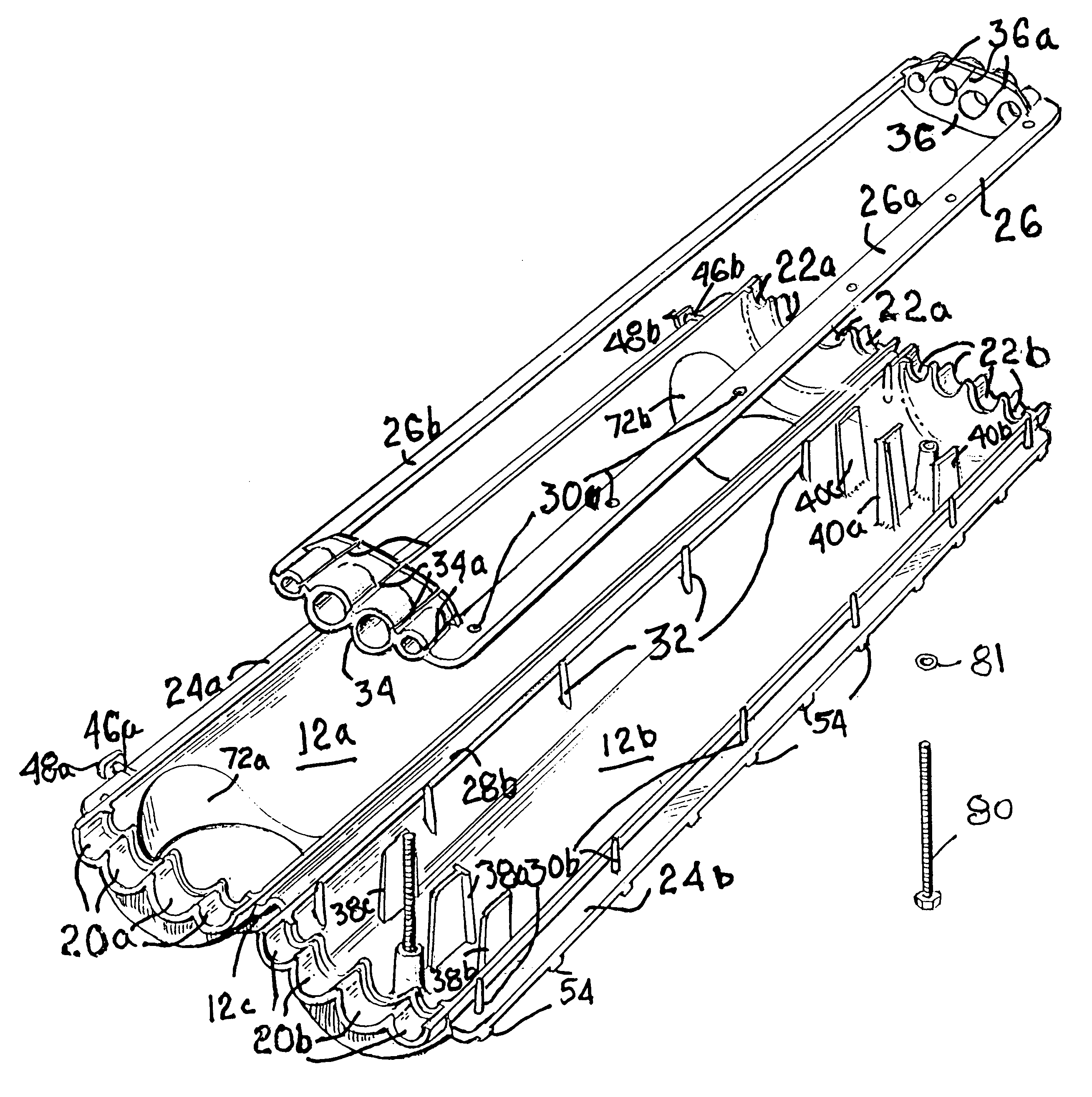
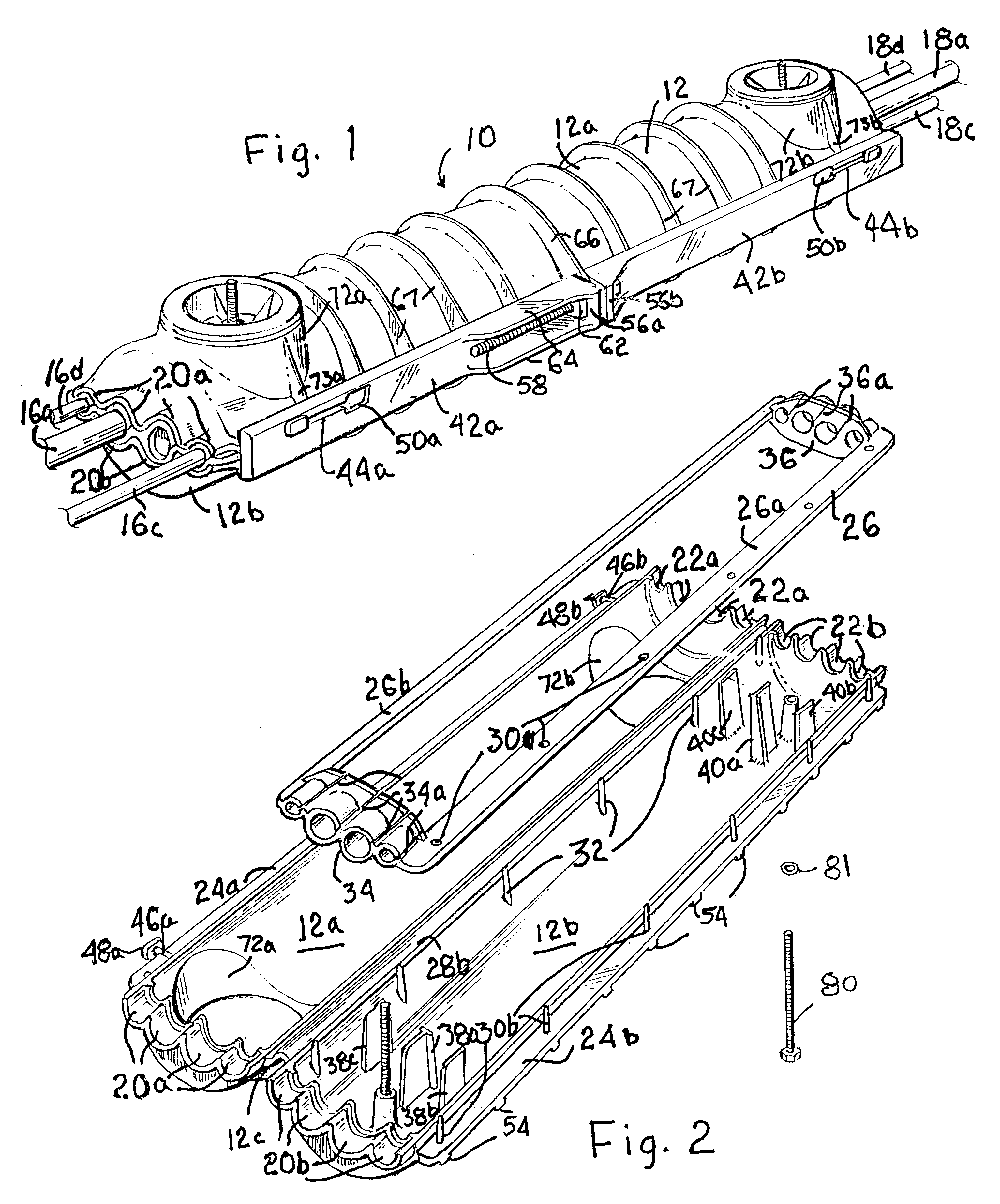
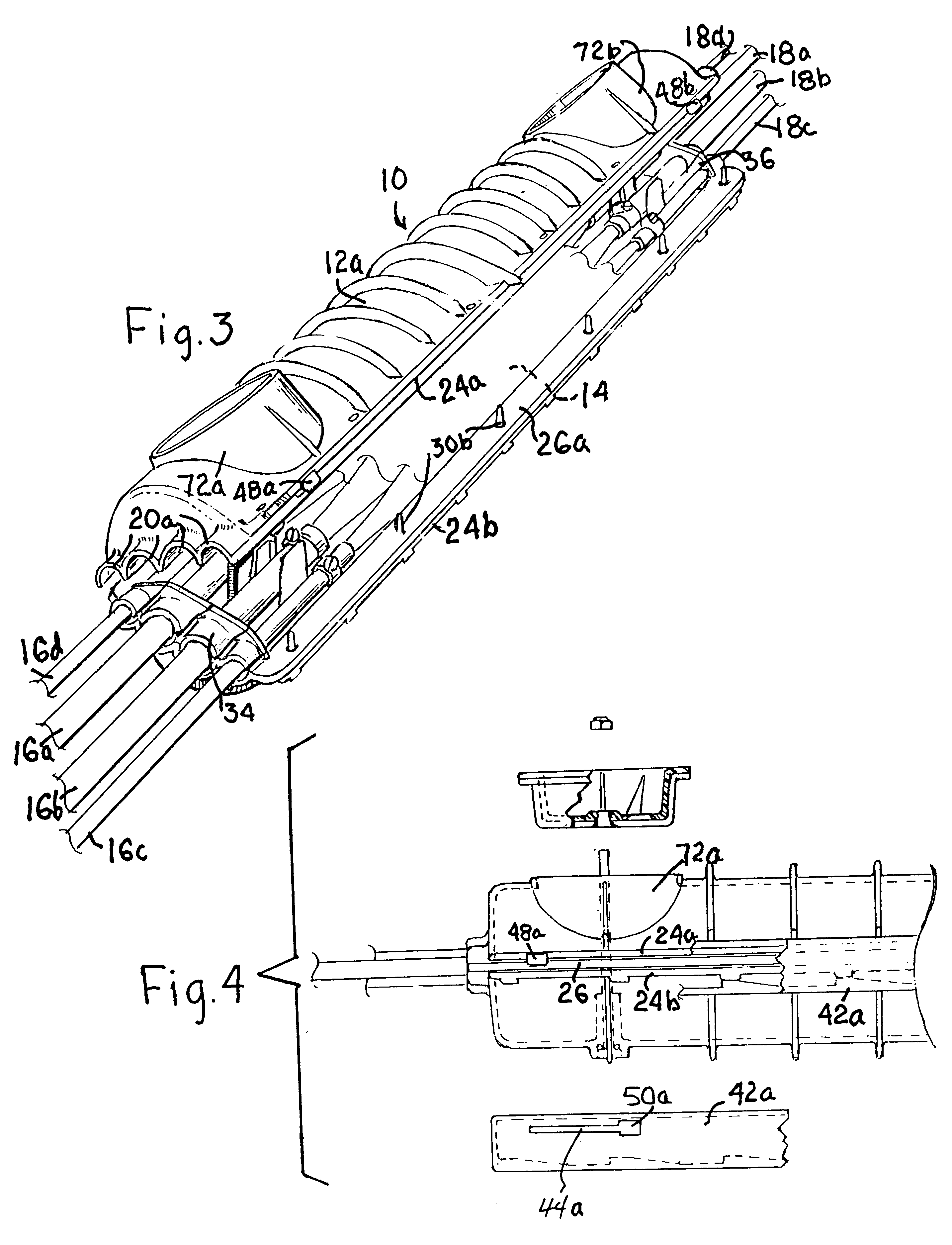
FIG. 1. shows a telephone line splice enclosure closed and with cables and splice enclosed and the procedure completed for sealing the housing for excluding moisture from the enclosed splice. The structure shown, while intended to be buried, may be used in another environment. The enclosure generally designated 10 comprises the housing 12 which is preferably composed of molded resinous material such as high density polyethylene and consists of an upper hollow housing part 12a and lower hollow housing part 12b. The two parts of the housing 12a and 12b may be separate from one another, but are preferably connected by an integral molded hinge 12c of the same material as the housing as shown in FIG. 2. Although the splice need not be shown in detail in the drawings, because the splice itself is conventional, its location 14 within the housing is indicated in FIG. 3. In the region 14 the splice is made up of individual connections of pairs of conductors from different cables 16a, 16b, 16...


PUM


Abstract

An elongated waterproof enclosure for spliced telephone cables is provided by a two-part molded resinous housing that provides openings for one or more cables at opposite ends. A one piece resilient sealing gasket includes longitudinally slitted tubular gaskets at the ends to snugly receive individual cables side by side. The grommets at each end are formed integrally and connected by flat connecting pieces arranged to be transverse to opposed narrow edges of the mating opposed housing portions. The narrow edges when clamped together pinch and seal the flat pieces. Housing ends conforming to the grommets also have opposed narrow edges which, when clamped together, pinch the grommets and provide a seal. The housing pieces are preferably connected along one side by an integral molded hinge offset from the opposed longitudinal edges to give the seal clearance. At the opposite side of the housing, offset from the edges, are rigid flanges molded integrally with the housing parts. The flanges lie generally parallel to one another when the housing is closed. Urged together by suitable clamping device, the flanges apply pressure to urge the opposed narrow edges together and into the gasket. A preferred clamping device is a channel-like member having cam elements on the opposed inside walls of the channel cooperating with cam elements on the flanges. A tubular port is provided through one of the housing parts and preferably provided with a closure which is piston-like and seals against the sidewalls of the cylindrical tubular port. Structure to draw the piston into the housing is connected between the piston and the housing. As the piston is drawn into the port against the insulating fluid filling the housing parts, the piston imposes pressure on the fluid to fill small spaces within the housing. A thinner part of the housing wall provides a pressure gauge designed to be forced outwardly as a protruding bubble when the pressure is sufficient to fill the voids as desired.

Description

THE NATURE OF THE INVENTIONThis invention relates to a telephone line splice enclosure which with little change is suitable for use with buried cable, underground conduits or suspended cables. Telephone cables may each include many wires and sometimes many cables are involved in a single splice. The enclosure of the present invention is preferably made large enough to accommodate splices of any sizes and provides sufficient openings for receiving multiple cables at each end.For many years splicing of telephone cables has been a job requiring accuracy and the patience of a skilled technician. Particularly if the splice of the connected cables is to be buried, special precautions need to be taken to make sure that the many electrical connections made within the splice are protected from moisture, dirt and atmosphere which might attack and destroy one or more of the connections. Any such failure can cause problems requiring unearthing the splice, repairing interrupted connections and r...

Claims


Application Information

Patent Timeline
IPC IPC(8): H02G15/00H02G15/10H02G15/113H02G15/013H02G15/117
CPCH02G15/013H02G15/113H02G15/117
Inventor MICHEL, JOHN M.
Owner MICHEL JOHN M
Why Eureka
Try Eureka