D-type flip-flop circiut

a flip-flop circuit and flip-flop technology, applied in the field of d-type flip-flop circuits, can solve the problems of high frequency operation trouble, inability to write data in time, and new input data takes an extra load for inverting old data

Inactive Publication Date: 2001-04-17
NIPPON PRECISION CIRCUITS
View PDF5 Cites 39 Cited by
  • Summary
  • Abstract
  • Description
  • Claims
  • Application Information

AI Technical Summary

Problems solved by technology

However, the D-type flip-flop circuit shown in FIG. 16 has had a trouble in its operation in high frequency because it has not been able to compensate a propagation delay time due to its structure.
Therefore, the new

Method used


Image

  • D-type flip-flop circiut
  • D-type flip-flop circiut
  • D-type flip-flop circiut

Examples


Embodiment Construction

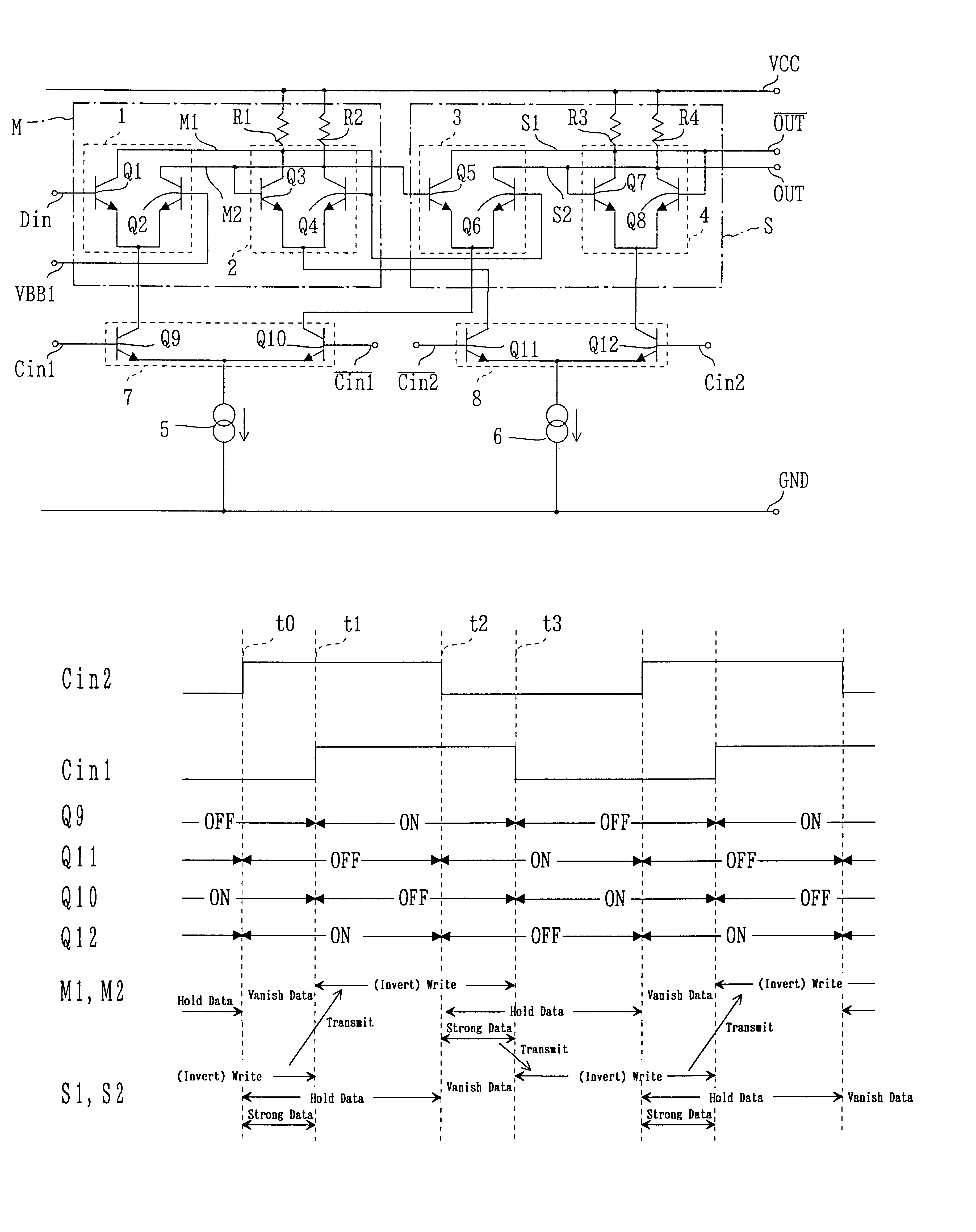
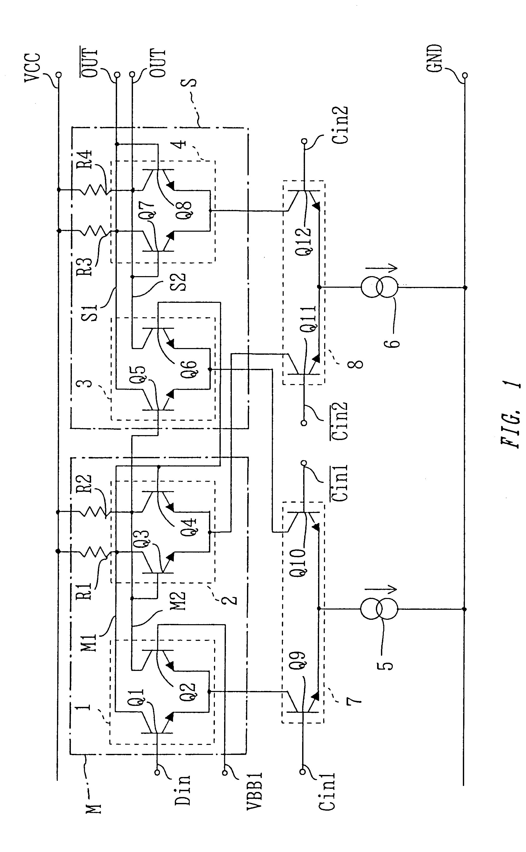
A D-type flip-flop circuit according to a first embodiment of the present invention will be explained below.

FIG. 1 is a circuit diagram showing a structure of the D-type flip-flop circuit of the present embodiment. The structure thereof will be explained at first with reference to the figure. A master circuit M comprises a first differential circuit 1 for inputting data and a second differential circuit 2 for holding data. A slave circuit S comprises a third differential circuit 3 for inputting data and a fourth differential circuit 4 for holding data. Here, the first differential circuit comprises transistors Q1 and Q2 whose emitters are connected in common, whose collectors are connected to a source terminal VCC via resistors R1 and R2, respectively, and whose bases receive signals from terminals Din and VBB1 as data, respectively. It is noted that the signal from the terminal VBB1 may be what is inverted from that from the terminal Din or one of them may be a reference potential....


PUM


Abstract

There is provided a D-type flip-flop circuit which is improved in terms of operating frequency. First and second current supplying circuits are provided as sources for supplying currents to first and third differential circuits for inputting data and to second and fourth differential circuits for holding data in a master circuit and a slave circuit. Further, timing for supplying the currents to the respective differential circuits for inputting and holding data are controlled by first and second clock signals, respectively. The D-type flip-flop circuit is improved in terms of operating frequency by optimizing timing for writing input data and timing for holding data by arranging the first clock signal so as to have a certain delay with respect to the second clock signal. Further, the D-type flip-flop circuit is improved with respect to the operating frequency also by optimizing the value of the currents supplied to the respective differential circuits.

Description

1. Field of the InventionThe present invention relates to a D-type flip-flop circuit.2. Description of Related ArtPresently, while a frequency dividing circuit operable for higher frequency is desired in the technology of a PLL frequency synthesizer, a master-slave type D-type flip-flop circuit composed of bipolar transistors (hereinafter referred to simply as a transistor) is being used.FIG. 16 shows a structure of such a D-type flip-flop circuit wherein a master circuit 161 comprises a differential circuit 162 for inputting data, a differential circuit 163 for holding data, a current supplying circuit 164 for supplying a current to the differential circuits 162 and 163 and a switching circuit 165 for alternately supplying the current to the differential circuits 162 and 163.The differential circuit 162 comprises transistors q1 and q2 whose emitters are connected in common, whose bases receive data which are signals inverted from each other and whose collectors are set as outputs. ...

Claims


Application Information

Patent Timeline
IPC IPC(8): H03K3/3562H03K3/00H03K3/289H03K3/286
CPCH03K3/289H03K3/3562
Inventor UENO, NAOKI
Owner NIPPON PRECISION CIRCUITS
Why Eureka
Try Eureka