Apparatus for and method of determining positional information for an object

a technology of position information and apparatus, applied in the direction of reradiation/reflection, radio wave reradiation/reflection, measurement devices, etc., can solve the problems of uncontrollable differential delay between corresponding range gates with respect to different antennas, inability to detect samplers, and relatively complex timing modules

Inactive Publication Date: 2001-04-17
CAMBRIDGE CONSULTANTS LTD
View PDF9 Cites 71 Cited by
  • Summary
  • Abstract
  • Description
  • Claims
  • Application Information

AI Technical Summary

Problems solved by technology

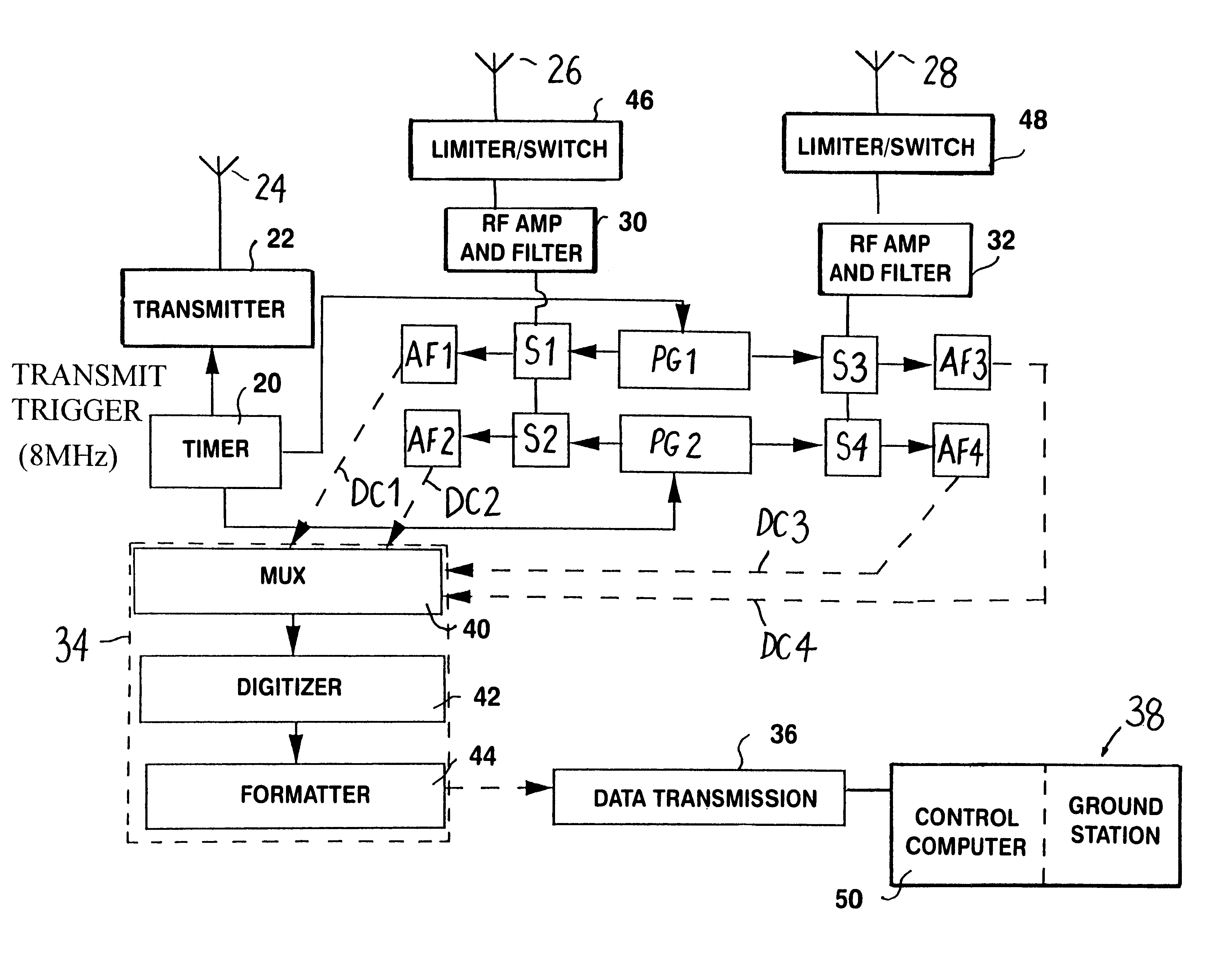
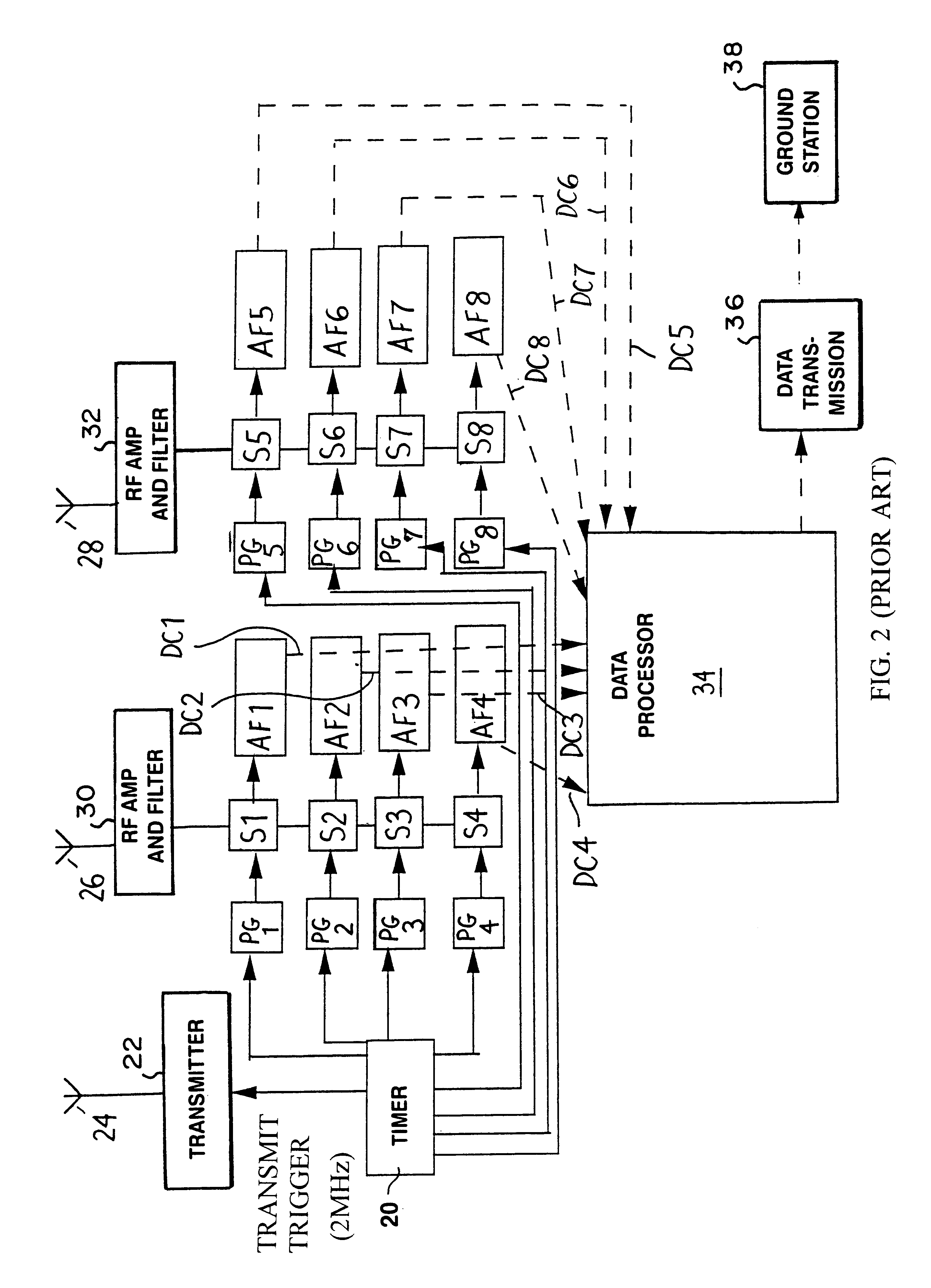
In the present context, particular points of interest are that each range gate of the apparatus requires its own sampler, pulse generator and audio frequency (AF) processing unit and that the existence of independent pulse generators means that the differential delay between corresponding range gates with respect to different antennas is uncontrolled.
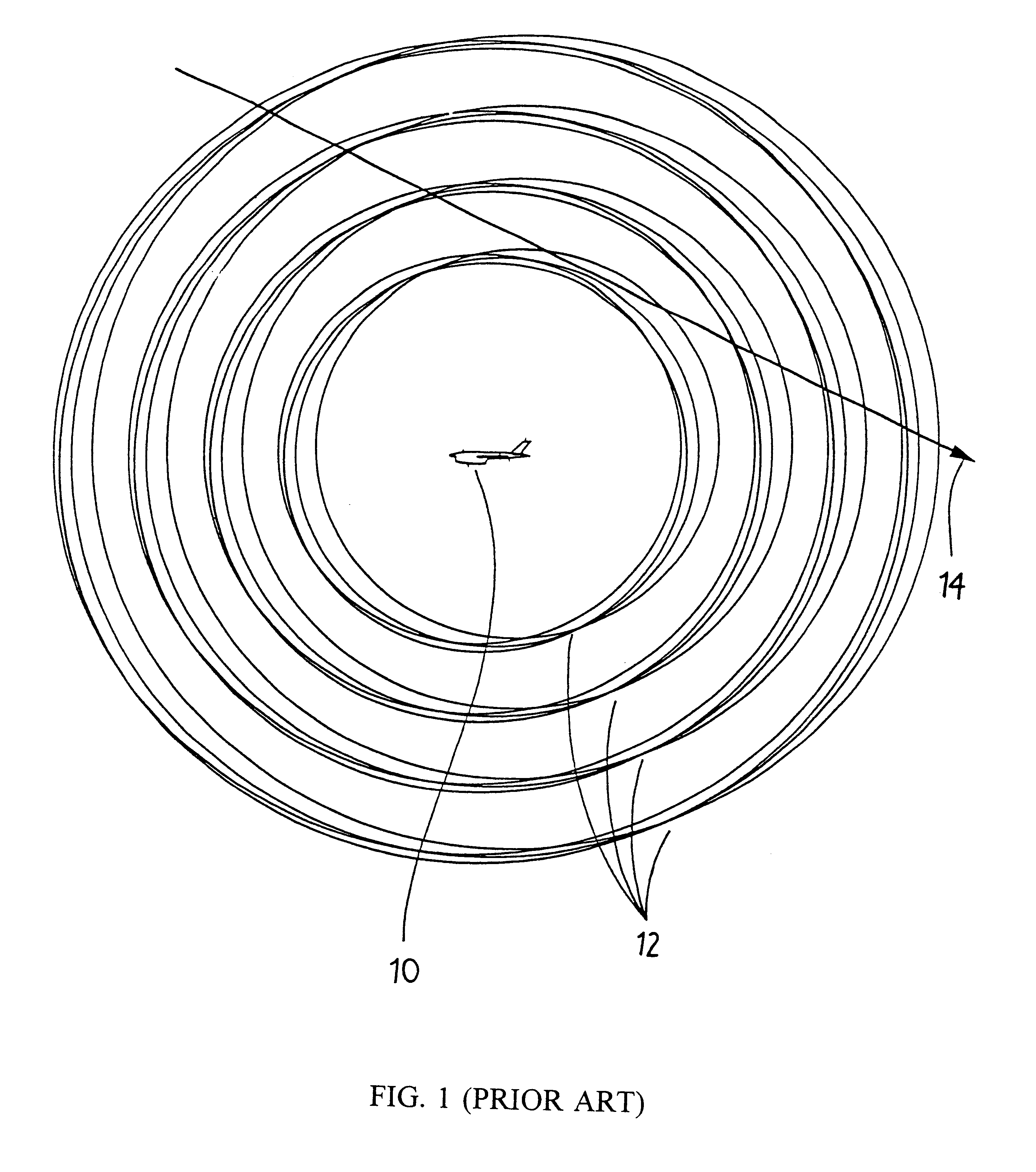
However, in practice only a single range gate is formed because the signal from a target decreases as the fourth power of range and so, quite deliberately, any reflection from previous probe pulses is arranged to be below the noise floor of the apparatus and is hence undetectable by the samplers.
Another feature of the prior art apparatus is that the timing module is fairly complex because each sampler for a receiver is driven with an independent clock which has to be set to the required delay between range gates.
This system while improving the performance had the disadvantages of requiring yet more circuitry for the autocalibration receiving means and timing generator, and of increasing the bandwidth of the signals required to evaluate target position.
Hence they have the disadvantage that until the full three dimensional trajectory of the target as a function of time has been computed, no representation of the three dimensional position of the target at a particular time is available; hence the processing is not real time.
Yet a further feature of these two known apparatuses is that the accuracy of position measurements deteriorates for smaller vehicles carrying the apparatus, to the point where they become unusable for very small vehicles.
This is because the known apparatuses measure the trajectory of the target with a precision determined by the minimum baseline of the antennas as installed, and thus the smaller the vehicle on which the system is mounted the less accurate the position measurement.
This too had the practical limitations that the accuracy was limited if the antenna separation was less than 1 m and the extra hardware required was expensive.
If the relative timing were detected for signals which are received at greatly different times, firstly the variation in the back-scatter due to the likely motion of the object could render the correlation process difficult or impossible to carry out accurately; this problem could be solved by keeping a library of likely return signals, and further correlating against these, although this may be undesirable.
Secondly, the correlation process would require to be carried out over a relatively long time span.
This would be computationally expensive.
The limiting may be partial or complete; in other words, either attenuation of the signal may occur if the power is too great, or the signal may be switched out altogether whilst it is of excessive power.

Method used


Image

  • Apparatus for and method of determining positional information for an object
  • Apparatus for and method of determining positional information for an object
  • Apparatus for and method of determining positional information for an object

Examples


Embodiment Construction

Overall Configuration for the Present Invention

Referring first to FIG. 4, three receivers 100, 102 and 104, are disposed at the vertices of a triangle but this is not fundamental so long as however many receivers are provided are at known locations. For simplicity, FIG. 4 shows just two range gates at the same delay with respect to the two receivers 100 and 102 (one gate per receiver); it should be noted that the range gates are not to scale. As is clear, the angle .theta. between the position at which the target (possibly a missile) crosses the range gate and the line joining the two receivers is a function of the distance between the range gates, which in turn is directly proportional to the different delay, .delta.t; the distance is a maximum when .theta. is 0 or 180.degree. and a minimum (zero) when .theta. is 90 or 270.degree.. In three dimensional terms a given angle .theta. would be representative of a target placed on a hyperboloid focused at the two receivers.

It is desirabl...


PUM


Abstract

Apparatus for determining positional information for an object transmits a probe signal towards the object. The probe signal as returned by the object is received at a plurality of spaced apart locations. The relative timing of the returned probe signals as received at the plurality of locations is detected, whereby positional information for the object can be determined. A number of realizations of the invention are disclosed.

Description

1. Field of the InventionThe present invention relates to apparatus for and a method of determining positional information for an object. The positional information might typically be angular orientation or attitude with respect to or range from a given datum.The invention has application in a number of fields including but not limited to automotive collision avoidance, intruder detection, and sensors in robotics for supporting motion in a complex and changing environment. One particular use for the invention is in a scoring system of the type which can provide a score for the proximity of approach of an object such as a small aircraft or intruder to a specified location such as a target aircraft or other detection location.The invention is described in detail later with reference to an electromagnetic sensor apparatus, and particularly with reference to short range electromagnetic sensing using short pulse, impulse systems (such as with pulses up to a few nanoseconds in duration). ...

Claims


Application Information

Patent Timeline
Patent Type & Authority Patents(United States)
IPC IPC(8): G01S13/00G01S13/02G01S13/87G01S13/18
CPCG01S13/003G01S13/0209G01S13/878G01S13/18
Inventor KERRY, NICHOLAS J.UTSI, PER A. V.UPTON, MILES E. G.PENFOLD, JUSTIN D. J.OSWALD, GORDON K. A.RICHARDSON, ALAN T.
Owner CAMBRIDGE CONSULTANTS LTD
Why Eureka
Try Eureka