Mobile communication system

a mobile communication and system technology, applied in multiplex communication, wireless communication, synchronisation arrangement, etc., can solve the problems of not involving the measurement of distance, the method of handling, and the frame synchronization of the chip plate unit, so as to measure the distance between the radio base station and the mobile station

Inactive Publication Date: 2001-04-17
TCL COMM TECH HLDG
View PDF13 Cites 39 Cited by
  • Summary
  • Abstract
  • Description
  • Claims
  • Application Information

AI Technical Summary

Benefits of technology

A mobile communication system according to a first aspect of the invention is constructed such that a time difference, eliminated by a fixed time difference, between a top time position of a burst received from a radio base station and a top time position of a burst transmitted so that the burst may arrive at the radio base station at the top of a time slot, and information of the measured time difference is notified to the radio base station. By the construction, a mobile communication system which can measure the distance between a radio base station and a mobile station accurately can be realized.
A mobile communication system according to a twenty seventh aspect of the invention is constructed such that, after frame synchronization between the radio base stations by time-divided CDMA control channels is established, the radio base station uses a time slot, in which the radio base station has received the time-divided CDMA control signal from the tributary base station, as a speech channel to down-links to a plurality of mobile stations. By this construction, time slots can be utilized effectively.

Problems solved by technology

However, those techniques don't involve measurement of the distance between a mobile station and a radio base station or synchronization between radio base stations by a chip rate unit.
However, the specification of U.S. Pat. No. 5,363,403 describes nothing of a method of handling a time-divided CDMA signal.
Furthermore, the specifications mentioned above describe nothing of frame synchronization by a chip plate unit of the time-divided CDMA system.
In order to utilize a GPS signal also in such a case, a complicated apparatus is required.
The conventional mobile communication systems have such problems as described above.

Method used


Image

  • Mobile communication system
  • Mobile communication system
  • Mobile communication system

Examples


embodiment 1

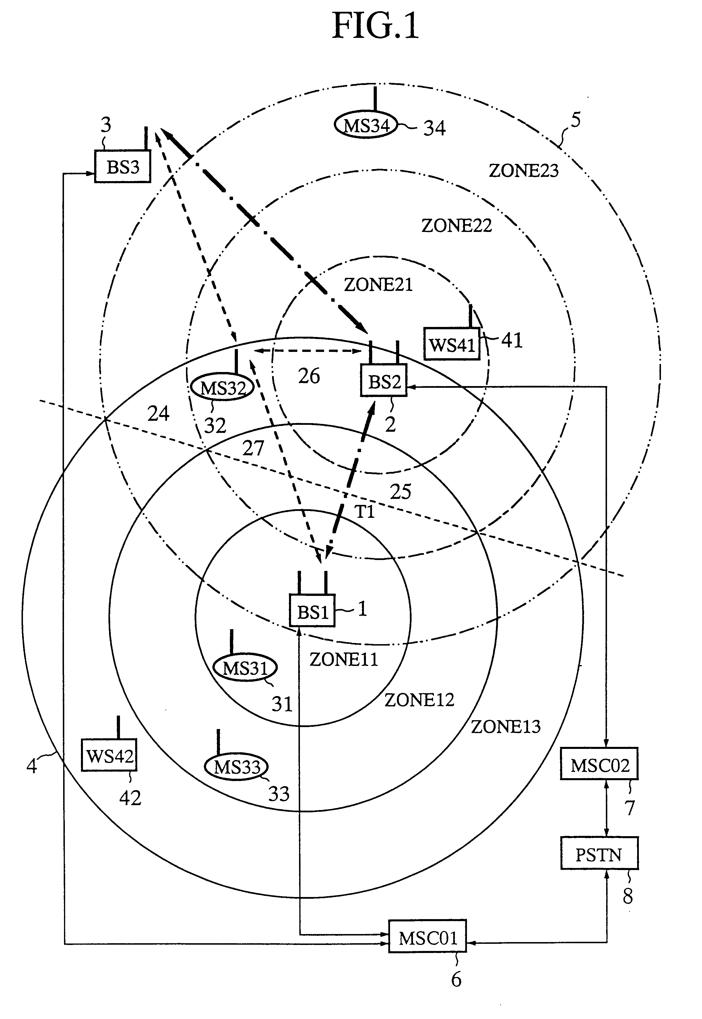
FIG. 1 is a system constructive view showing a general construction of a mobile communication system to which a time slot sharing and frequency channel sharing system according to the present invention is applied. Referring to FIG. 1, reference numerals 1, 2 and 3 denote each a radio base station, and 4 and 5 denote each a radio cover area (hereinafter referred to as cell) constructed by the radio base station 1 or 2. It is to be noted that the cell 4 includes zones 11, 12 and 13, and the cell 5 includes zones 21, 22 and 23. Reference numerals 31, 32, 33 and 34 denote each a mobile station (MS) such as a mobile vehicle carried communication apparatus, a mobile portable communication apparatus or the like which communicates with the radio base station 1 or 2 over a radio channel. Reference numerals 41 and 42 denote each a WLL station (WS) which communicates with the radio base station 1 or 2 over a radio channel.

Reference numeral 6 denotes a mobile switching center (MSC) which contro...

embodiment 2

Subsequently, as an embodiment 2 of the present invention, measurement of the distance to a moving mobile station in a time-divided CDMA system is described.

FIG. 7 is a diagrammatic view illustrating an example of a frame structure of a TDMA / time-divided CDMA communication system for a PCS in the present embodiment 2. This frame structure is similar to that of the PHS (Personal Handy Phone System: a cordless system used in Japan), but is a little different in structure of time slots. In particular, the voice codec rate is assumed to be 16 kb / s, 8 kb / s or 4 kb / s. The data transmission rate is 192 kb / s, and the information rate per one time slot is 23.2 kb / s. By setting the chip rate to 192 kb / s.times.128=24.576 Mb / s, data of 192 kb / s mentioned above are spectrum-spreaded with orthogonal spread-spectrum codes having this chip rate. Accordingly, a plurality of time-divided CDMA signals having different orthogonal spread-spectrum codes in one time slot share a frequency channel, and the...

embodiment 3

Subsequently, as an embodiment 3 of the present embodiment, a mobile station hand-over system under a condition that radio base stations are installed not at equal distances is described.

Hand-over which changes over a mobile station to the nearest radio base station is usually performed based on electric field strengths of received signals from the mobile station or radio base stations.

However, in a mobile communication system in which the distances between radio base stations are not necessarily equal to each other such as where radio base stations of different operators are installed in a mixed condition and cells (radio cover areas) of them overlap with each other or where a large number of radio base stations are installed in a arrow area because of the communication loads, the following situation exists: it cannot be discriminated that the distance from a mobile station to a neighboring radio base station is shortest when the transmission power to the mobile station or the radi...


PUM


Abstract

A mobile communication system wherein a mobile station measures the distances between the mobile station and a plurality of adjacent radio base stations each from a time difference, eliminated by a fixed time difference, between the top time position of a time-divided CDMA burst signal received from a radio base station and the top time position of a time-divided CDMA burst signal transmitted to the radio base station in response to an instruction from the radio base station so that the top of the time-divided CDMA burst signal may come to the top time position of a time slot, and utilizes a result of the measurement for a hand-over discrimination, and frame synchronization between the radio base stations is established with a high degree of accuracy so that a plurality of radio base stations may operate in a same frame synchronization condition.

Description

This invention relates to a mobile communication system which realizes frequency channel sharing or time slot sharing using a time division multiple access (hereinafter referred to as TDMA) system or a time-divided code division multiple access (hereinafter referred to as time-divided CDMA) system, and more particularly to measurement and utilization of the distance between a radio base station and a mobile station or between radio base stations, and acquisition and keeping of frame synchronization between a radio base station and a mobile station or between radio base stations.A mobile communication system is formed principally from, for example, mobile vehicle-carried communication apparatus, mobile portable communication apparatus or like apparatus (hereinafter referred to as mobile stations) and radio base stations which communicate with the mobile stations by radio channels. In such a mobile communication system, sharing of a same radio frequency spectrum by different radio sys...

Claims


Application Information

Patent Timeline
Patent Type & Authority Patents(United States)
IPC IPC(8): H04Q7/38H04W36/08H04W36/18
CPCH04W36/0072H04W56/0025H04W36/32
Inventor UCHIDA, YOSHINORISUZUKI, KUNIYUKI
Owner TCL COMM TECH HLDG
Why Eureka
Try Eureka