Lumber feed system with load responsive speed modulation

Inactive Publication Date: 2001-04-24
BID GRP TECH LTD +1
View PDF31 Cites 26 Cited by
  • Summary
  • Abstract
  • Description
  • Claims
  • Application Information

AI Technical Summary

Benefits of technology

An object of the present invention is to overcome the performance limitations of board and cant separating feeders presently in use, by means of an auxiliary system

Problems solved by technology

Inadequate regulation of the incoming lumber flow can produce opposite negative effects such as, on the one hand, lack of material at the loading point or, on the other hand, overlapping of pieces due to pressure build

Method used


Image

  • Lumber feed system with load responsive speed modulation
  • Lumber feed system with load responsive speed modulation
  • Lumber feed system with load responsive speed modulation

Examples


Embodiment Construction

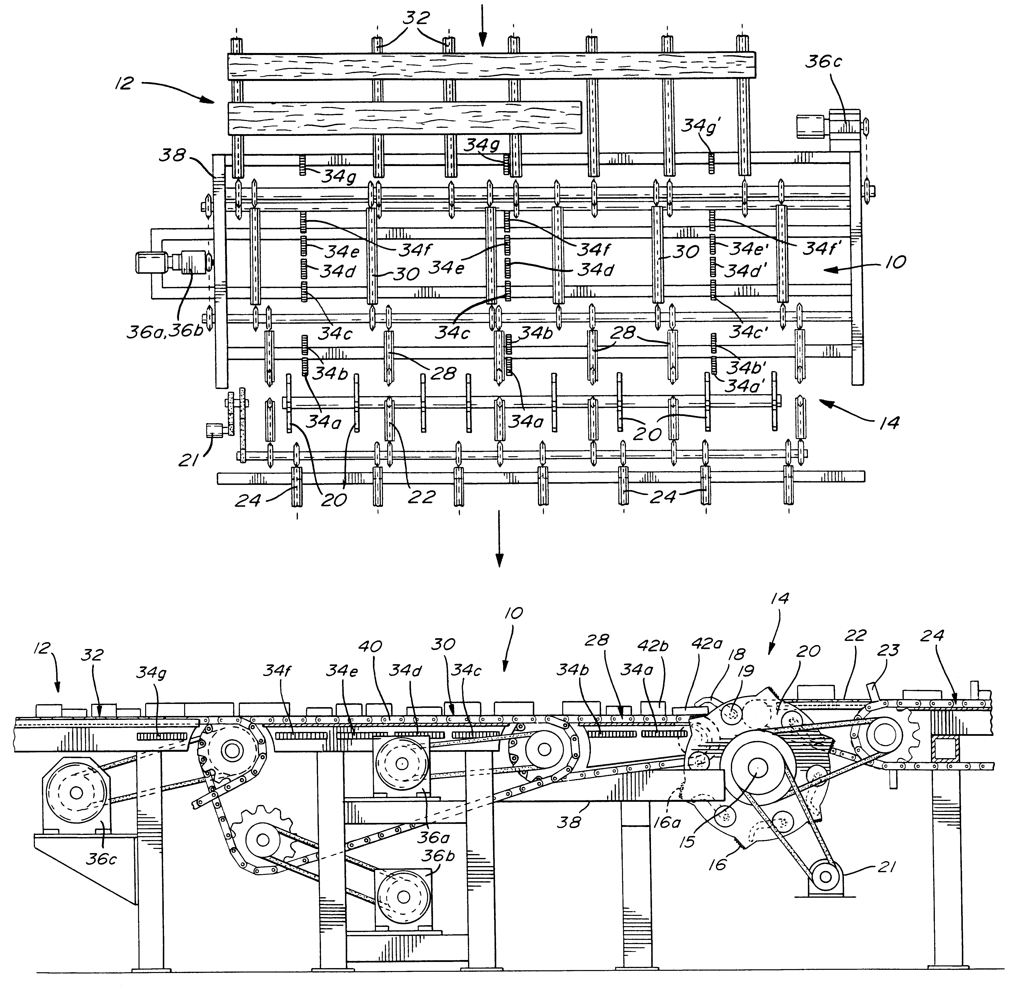
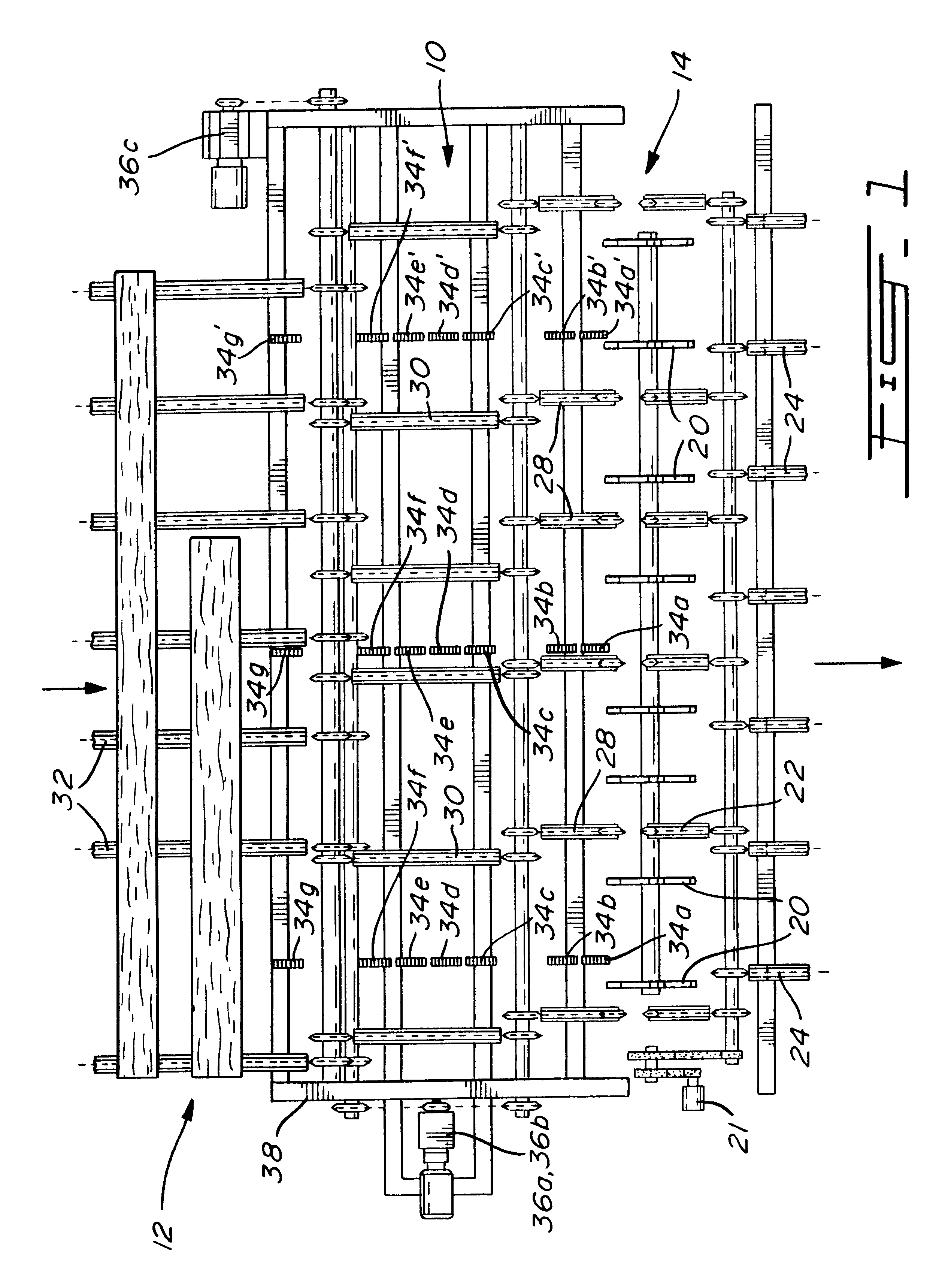
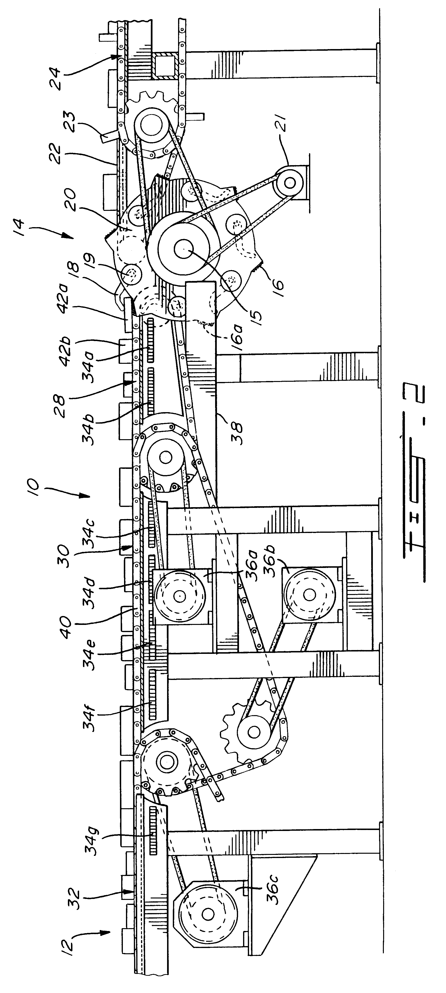
As illustrated in FIGS. 1 and 2, the infeed control system 10 which is the object of the present invention, consists basically of a fixed frame 38 supporting at least two transfer sections 28 and 30, section 28 being shorter than section 30. These sections comprise a multiplicity of parallely disposed carrying chains 40, having a serrated top portion 41, plus an array of sensing elements such as, for example, photoelectric cells 34a to 34f, arranged in at least two lines at longitudinal spacings suitable for their purpose. The distance laterally separating the first two lines of sensors 34a-34f is shorter than the minimal length of a lumber piece processed. A further line of sensors 34a' to 34f' may be required to the right of sensors 34a-34f for longer lumber pieces.

In a preferred form of the invention, the drive units of the individual sections of the control transfers are electric servo-motors having a maximum torque capacity, in either direction of rotation, of more than twice t...


PUM


Abstract

The disclosure describes a system to provide a steady supply of lumber pieces to a board separating device and insure the correct positioning of each lumber piece, at the proper time, thus allowing the separating device to function at a substantially higher rate than hitherto possible with previously known infeeding arrangements.

Description

The present invention relates to a system to be used as a load sensor and regulator, in front of a high piece count transversal type lumber separator such as, for instance, the one described in U.S. Pat. No. 5,518,106 (B. Allard), dated May 21, 1996. The incoming material consists of four-faced or two-faced lumber pieces carried forward laterally in a single layer by parallel chains, towards the separator whose function is to pick out individually each piece of lumber from the incoming stream and to deposit it in turn between rows of lugs affixed on parallel carry-off chains synchronized with the offloading sequence of the separator.Among the transversal type lumber separators in use today, the apparatus which is the object of the heretofore quoted US patent is considered one of the most efficient performers in the industry, being known to reach piece counts up to 120 per minute, in its original mode of installation. Performance figures, however, have so far been largely influenced ...

Claims


Application Information

Patent Timeline
IPC IPC(8): B27B31/06B27B31/00B65G47/31B65G43/08
CPCB27B31/006B27B31/06B65G43/08B65G47/31
Inventor GAGNON, ANDREBRISSON, MAURICE
Owner BID GRP TECH LTD
Why Eureka
Try Eureka