Method for automatically smoothing object level of detail transitions for regular objects in a computer graphics display system

a computer graphics and display system technology, applied in the field of computer graphics rendering systems, can solve the problems of affecting the performance of the computer graphics system, affecting the quality of the object, and drastically altering the polygonal or pixel requirements

Inactive Publication Date: 2001-04-24
CHRISTOFFERSON ENTERPRISES
View PDF4 Cites 67 Cited by
  • Summary
  • Abstract
  • Description
  • Claims
  • Application Information

AI Technical Summary

Problems solved by technology

The performance limitations of a computer graphics system are most poignant in real-time situations, where scene complexity is limited by the specific amount of time available to generate the image.
Polygon processing usually dominates the front-end of the pipeline, and is often the limiting factor for the transition between database loading and rendering.
One of the challenges of designing computer graphics systems is that simply changing the viewing position of a static database can drastically alter the polygonal or pixel requirements.
For real-time situations, solutions which vary widely in effectiveness depending on viewing position are of questionable value, since the worst case is always the constraint limiting performance.
The problem this creates is that perspective scenes of a relatively balanced distribution of objects concentrate object density in the distance.
However, most applications cannot limit the viewing distance arbitrarily, as this method obviously limits the depth of view.
There are two problems with this solution.
Forcing a false perspective is disconcerting and may have negative human factors considerations.
Secondly, limiting the field of view can severely hamper immersion in a scene.
Although useful, these methods have several serious drawbacks for real-time situations.
First and foremost, they mitigate scene complexity only in certain situations, and are subject to complete breakdown for many scenes, which is unacceptable for real-time environments.
Secondly, many of the algorithms require occlusion preprocessing, which is both computationally and representationally demanding for large databases.
Finally, hybrid solutions require a two-stage rendering process with buffer and object processing feedback, an unrealistic demand on current generations of graphics hardware.
By itself, this method is unsuitable for arbitrary scene reduction.
This introduces one of the chief drawbacks of LOD implementations, transition anomalies.
The second major drawback of the LOD approach is the need for additional database resources, where each level of detail requires independent object descriptions, increasing the size and complexity of the geometric database.
This creates a non-deterministic and thus inconsistent criteria for the selected object display.
In all cases, LOD transitions create varying levels of undesirable visual anomalies.
There are two classes of problems commonly associated with LOD transitions.
One is caused by the rapid change from one representation to another, which is distracting to the viewer.
This change is even more noticeable to the viewer, as it usually results in high-contrast visual transitions called holes, or cracks.
This severely limits the range of attributes of the terrain, and is thus practically unusable.
These can create abrupt nonconformal geometries.
Sorted transparency is often either expensive or not available in hardware.
However, haze use by its nature must be limited, else it create an effect similar to an abrupt far clipping plane.
None of these solutions address a fundamental problem of geometric transitions: the attribute data corresponding to colors and textures applied to geometry at multiple levels of detail has no method for safe interpolation of arbitrary attributes.
Technology and cost considerations in practice impose design constraints on image generation systems demanding compromises in visual complexity and quality.
This creates a problem the same as that created by projecting satellite orthophotos to terrain data, as has been common in military simulators for over a decade.
Detail is not captured with equal area precision for geometries with excessive variation in the plane perpendicular to the viewing direction, resulting in smearing during reconstruction.
This method requires relatively large amounts of texture storage.
Full implementation limits dynamic lighting effects, also due to the prerendered LOD's.
One modification is that in many situations an orthographically derived multiple LOD texture would not suffice.

Method used


Image

  • Method for automatically smoothing object level of detail transitions for regular objects in a computer graphics display system
  • Method for automatically smoothing object level of detail transitions for regular objects in a computer graphics display system
  • Method for automatically smoothing object level of detail transitions for regular objects in a computer graphics display system

Examples


Embodiment Construction

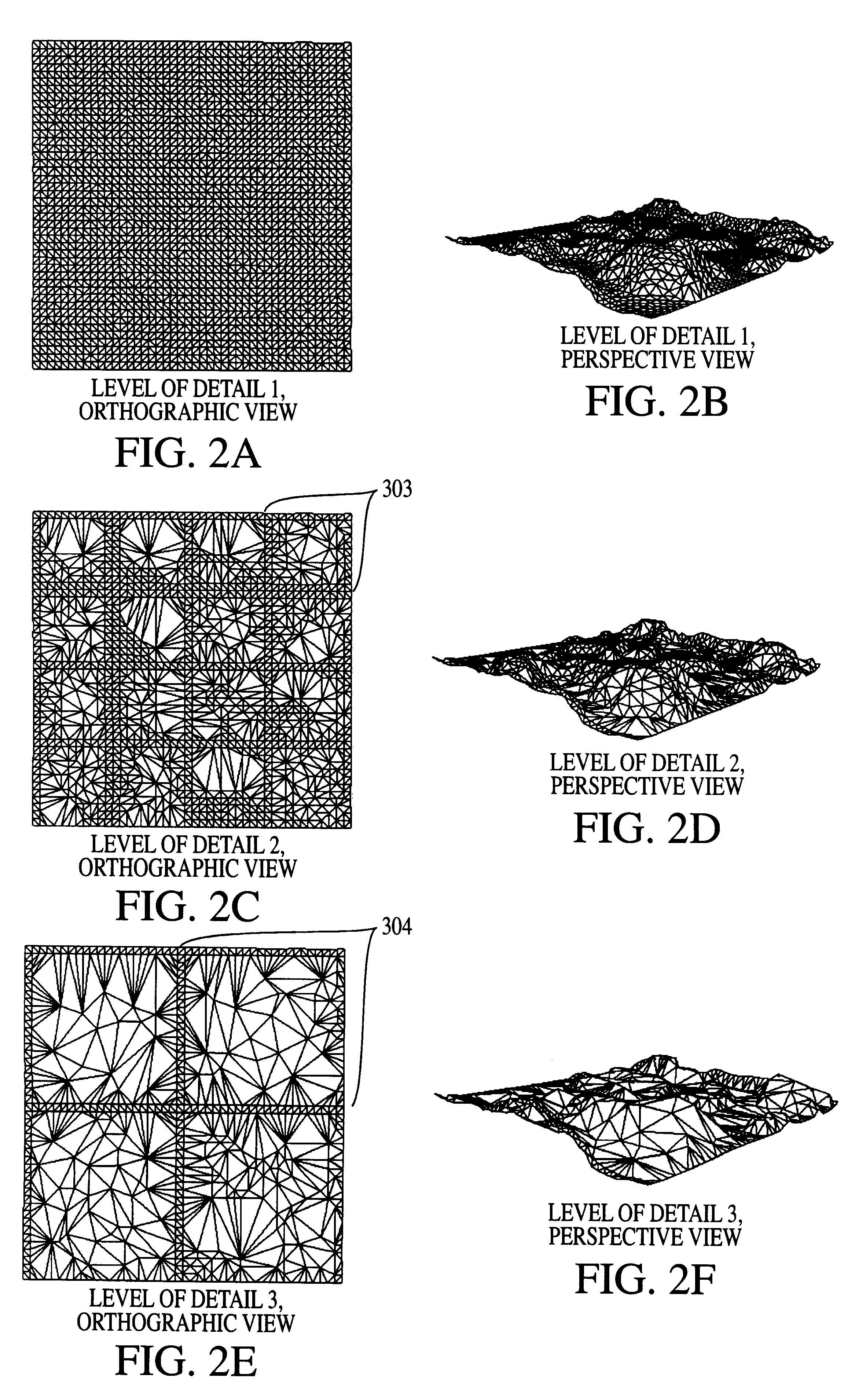
Referring now to the drawings, and more particularly to FIG. 2, there is shown orthographic and perspective views for each level of detail of an implementation of the invention using three levels of detail for a terrain database. The invention is practiced in the following steps.

1) Create a base regular grid of 3D datapoints. This will comprise the total vertex list.

2) Create conformally optimal polygonalization of this vertex list.

3) Create desired partitioning for first level reduction of database into regular grids, called sectors.

4) Perform conformal decimation, fixing points on the perimeter of each sector grid. The second level of detail is often decimated only to the point of eliminating coplanar polygons. This reduces polygons while avoiding geometric anomalies while transitioning the near zone to texture detail.

5) For successive levels of detail reduction, create higher level groupings of fixed grids, such as quads of the previous level (as shown in FIG. 2, where each of th...


PUM


Abstract

A database and execution hierarchy for computer graphics display systems that breaks LOD transitions into two functional steps. The first is the geometry transition, and the second is the detail transition, provided by texture maps. The geometric transition applies conformal fixed vertex decimation methods to create multiple levels of detail with a shared vertex coordinate database. Transitions between LOD's are made seamless by creating the multiple LOD levels with macrogrids of fixed, non-decimated vertices. These are generated using a hierarchical approach that reduces the number of fixed points in the macrogrid at each successive level. Visual anomalies associated with color and texture transitions are reduced by using texture maps to ensure consistent detail transitions for pixels between LOD's. The textures capture the detail information of the highest LOD using orthographic rendering on a grid matching the geometric macrogrid. Database storage size and transmission rate are optimized. Vertex storage is minimized by reuse for cospatial LOD's. Surface normal descriptions can also be eliminated, saving substantial additional space, and reducing the setup calculations for a large portion of the scene since lighting is precalculated and can be disabled for higher LOD's. Texture indices can also be reused for grouped LOD's.

Description

1. Field of the InventionThe present invention generally relates to computer graphics rendering systems for the creation and display of arbitrarily complex scenes, and in particular to methods for improving the apparent performance of such systems under the constraints imposed by operation in real-time.2. Background DescriptionComputer systems designed to generate images often are comprised of various stages that can be implemented in combinations of hardware and software. Although there are a great variety of implementations, in general all systems are similar in function. At the coarsest level, computer graphics systems consist of two major components: a database to describe the geometric entities which need to be created, and the rendering pipeline, which transforms this database into a displayed image.The performance limitations of a computer graphics system are most poignant in real-time situations, where scene complexity is limited by the specific amount of time available to g...

Claims


Application Information

Patent Timeline
Patent Type & Authority Patents(United States)
IPC IPC(8): G06T15/10G06T15/20G06T15/04
CPCG06T15/04
Inventor CHRISTOFFERSON, CARL L.CHRISTOFFERSON, FRANK C.
Owner CHRISTOFFERSON ENTERPRISES
Why Eureka
Try Eureka