Drum brake device

a technology of drum brakes and rotors, which is applied in the direction of brake elements, slack adjusters, braking members, etc., can solve the problems of increasing the cost of the device, increasing the resistance, and dragging of the brake shoe, so as to reduce the chance of misassembly and assembly, reduce the cost, and reduce the effect of components

Inactive Publication Date: 2001-05-01
NISSHINBO IND INC
View PDF7 Cites 4 Cited by
  • Summary
  • Abstract
  • Description
  • Claims
  • Application Information

AI Technical Summary

Benefits of technology

This invention was designed to resolve the above disadvantages. To that end, an object of the invention is to provide a drum brake device which has fewer components and therefore is less expensive, and which decreases chances of misassembling the device.
Another object of this invention is to provide a drum brake device which facilitates the pre-mounting of a long link.

Problems solved by technology

The extra components, namely, the pivot sleeve p and E ring q, required to pre-mount the pivot lever i onto the brake shoe e increase the cost of the device.
As shown in FIG. 21, the pivot sleeve p is installed such that its flange r lies between the shoe web u and the bottom face of the plate spring t which forms part of the shoe hold mechanism s. Therefore, a different holding force would be generated on the left and right brake shoes d, e if the left and right shoe hold mechanisms were of the same dimensions, thereby increasing the resistance of the brake shoe e with attached pivot lever i to extend or contract, possibly causing the brake shoe to drag or creating other problems thereof.
The greater number of components coupled with different specifications for certain similar components would not only make the device more expensive but create chances of misassembling the device.

Method used


Image

  • Drum brake device
  • Drum brake device
  • Drum brake device

Examples


first embodiment

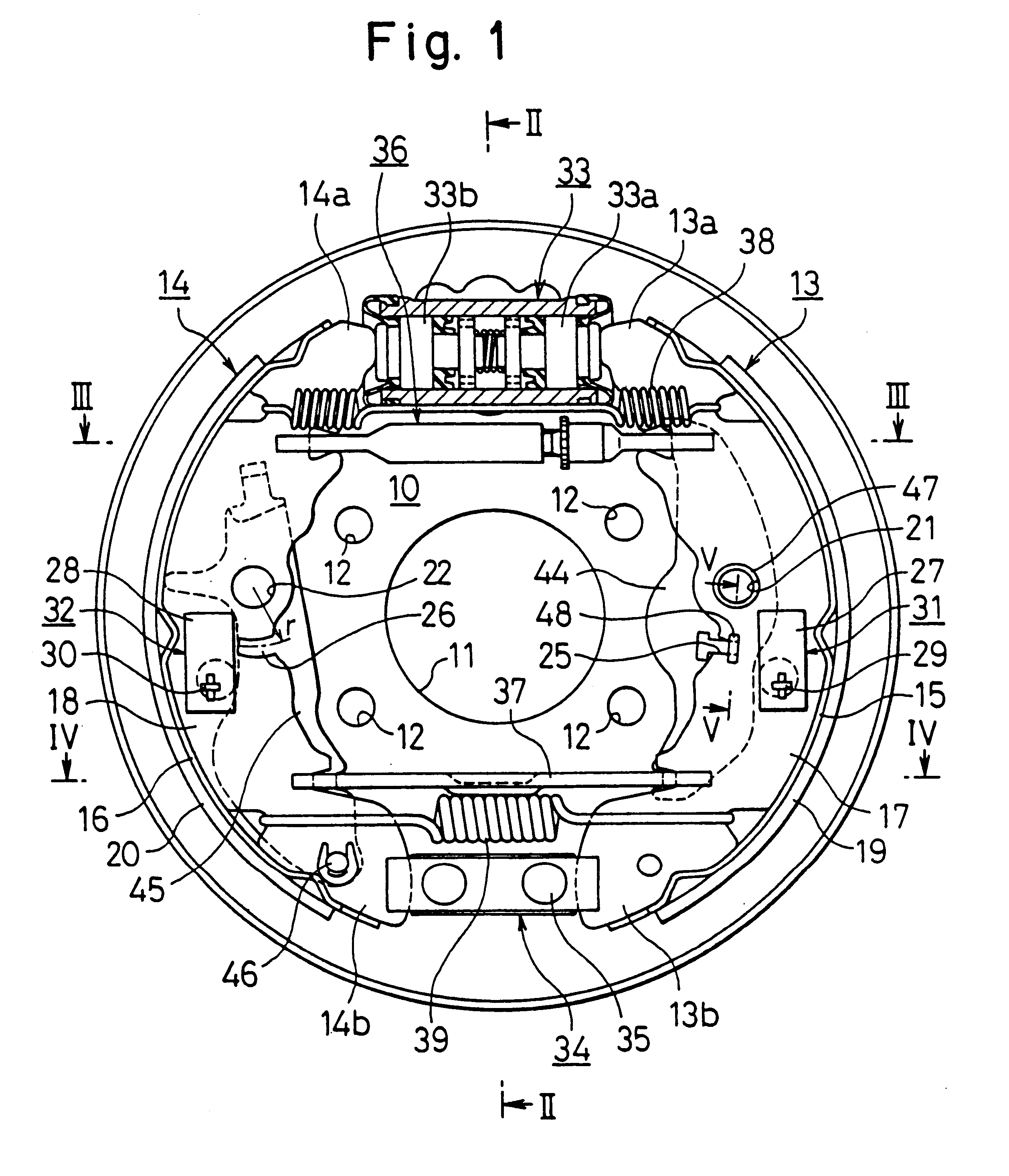
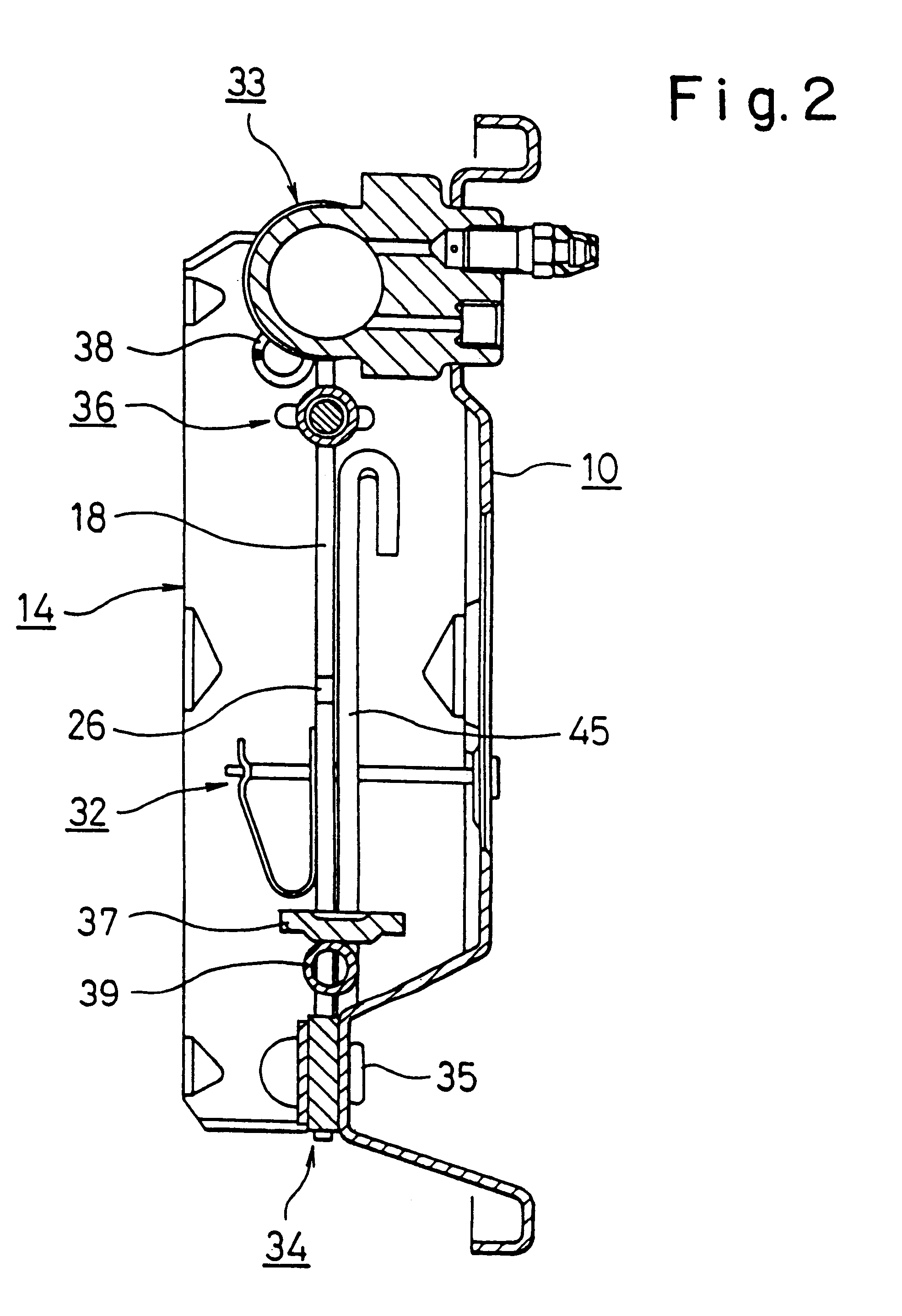
this invention is explained as based on the configurations of FIG. 1 to FIG. 8. The drum brake device includes a backplate 10.

The central hole 11 of the backplate 10 is freely inlaid in the vehicle axle, and the backplate 10 is then affixed to a stationary member of the vehicle by bolts inserted through plural bolt holes 12. A pair of brake shoes 13, 14, are provided each including a shoe web 17, 18 joined to the inner side of a curved shoe rim 15, 16 so as to form a "T" in cross section, and a lining 19, 20 affixed around the perimeter of the shoe rim 15, 16. A pivot hole 21, 22 is bored in the virtual center of each shoe web 17, 18, and a notched groove 25, 26 is formed below each pivot hole 21, 22, respectively. The notched grooves 25, 26 are each formed in the shape of an arc of equal radius r from the center of the pivot hole 21, 22. Each brake shoe 13, 14 is elastically mounted on the backplate 10 by a conventional shoe hold mechanism 31, 32. The shoe hold mechanism each compr...

example 2

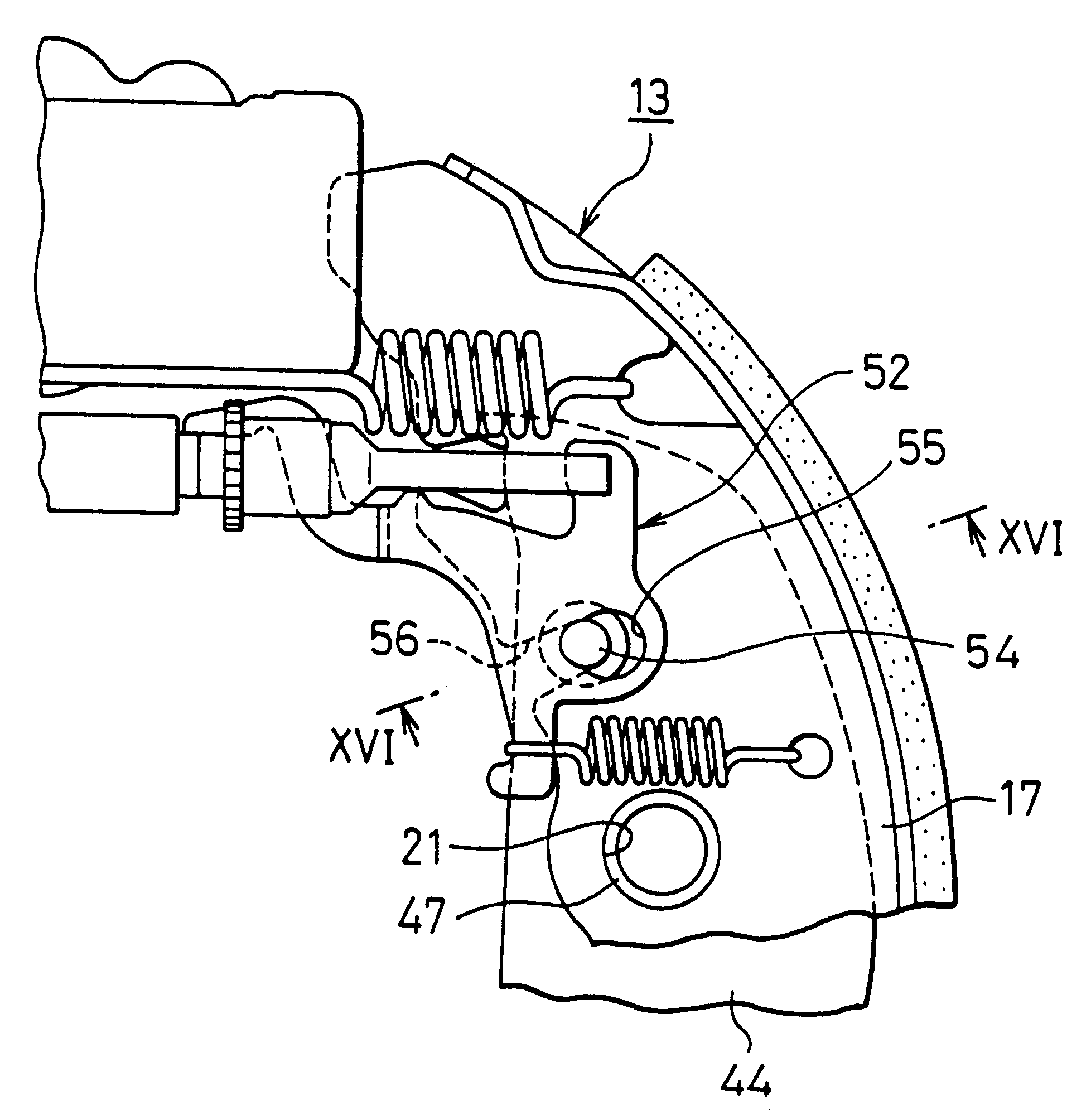
FIG. 9 illustrates the pivot member of the long link 44 and the shoe web 17, and the engagement thereof in cross section. In this configuration, the engagement hook 48 is formed on the shoe web 17 of the brake shoe 13, and the notched groove 25 is formed in the long link 44. Moreover, the protuberance 47 can be formed on the shoe web 17, and the pivot hole 21 can be bored in the long link 44.

example 3

FIG. 10 and FIG. 11 illustrate another embodiment of this invention in which T-shaped engagement holes 50, 51 are bored in each shoe web 17, 18 respectively in place of the notched grooves. The stem segments of the T-shaped engagement holes 50, 51 are curved and formed at a radius r1 from the center of the central pivot holes 21, 22. In addition, a short-stemmed T-shaped engagement hook 48 is provided vertically on the back edge of the long link 44. Aside from this configuration, a single T-shaped engagement hole 50 can be bored in the one brake shoe 13 on which the long link 44 is to be attached.

To pre-mounted the long link 44 onto the brake shoe 13, the front tip of the engagement hook 48 of the long link 44 is inserted into the wide part of the T-shaped engagement hole 50, then rotated clockwise with the pivot member formed by the protuberance 47 and the pivot hole 21 as the fulcrum, until it abuts the bottom of the curved stem 50b of the engagement hole 50.

This configuration fac...


PUM


Abstract

A drum brake device is provided which facilitates the pre-mounting of a long link, without increasing the number of components or the cost of the device. The long link (44) is pivotable on the central segment of one brake shoe (13). An engagement hook (48) protrudes from one or the other of the long link (44) or the one brake shoe (13). A notched groove (25) is formed in the other component thereof. The engagement hook (48) is inserted into the notched groove (25). The rotation of the long link (44) relative to the one brake shoe (13) will cause the long link (44) and one brake shoe (13) to be superimposable and detachable.

Description

This invention relates to a drum brake device that functions as a leading-trailing (LT) type when the service brake is applied, and as a duo-servo (DS) type when the parking brake is applied. More specifically, it relates to a drum brake device in which the configuration facilitates the assembly of the device.This type of drum brake device has been disclosed, for example, in U.S. Pat. No. 5,275,260, and is explained with reference to FIG. 20 and FIG. 21. A hydraulic cylinder b and an anchor block c are provided on the upper and lower segments of the back plate a respectively. The upper and lower ends of a pair of left and right brake shoes, d, e, engage the hydraulic cylinder b and the anchor block c, respectively. A first shoe return spring f and a second shoe return spring g are stretched between the lower and upper ends f the brake shoes d, e respectively. The parking brake lever h is pivoted on the lower segment of the left brake shoe d. A pivot lever i is pivoted such that its ...

Claims


Application Information

Patent Timeline
Patent Type & Authority Patents(United States)
IPC IPC(8): F16D65/38F16D65/09F16D65/04F16D65/56F16D51/24F16D51/00F16D51/50F16D51/48
CPCF16D51/24F16D51/50F16D65/091F16D65/563
Inventor ASAI, SEIJIKOBAYASHI, YASUSHI
Owner NISSHINBO IND INC
Why Eureka
Try Eureka