Piezoelectric actuated valve with membrane chamber

a technology of actuation valve and membrane chamber, which is applied in the direction of machine/engine, device details, and piezoelectric/electrostrictive device details, etc., can solve the problems of length change compensation and loss of pressure chamber fluid

Inactive Publication Date: 2001-05-01
ROBERT BOSCH GMBH
View PDF6 Cites 3 Cited by
  • Summary
  • Abstract
  • Description
  • Claims
  • Application Information

AI Technical Summary

Benefits of technology

The valve according to the invention, has the advantage over the prior art that the pressure chamber suffers no fluid loss. A disadvantageous length change of the entire device is thus prevented, even if the piezoelectric actuator, the valve, or the housing changes its length, for example upon heating. Furthermore, the device has a simple design and a secure and reliable seal can be produced.A number of exemplary embodiments of the invention are shown in the drawings and will be explained in more detail in the description below.FIG. 1 shows a fuel injection valve in a sectional view,FIG. 2 shows a first exemplary embodiment of a pressure intensifier with a fluid refill valve,FIG. 3 shows a second type of pressure intensifier with a refill valve, andFIG. 4 shows a third type of pressure intensifier, likewise with a refill valve.

Problems solved by technology

With valves of this kind, there is the problem of compensating for length changes of the piezoelectric actuator, the valve, or the valve housing by means of the hydraulic coupling chamber, which will be referred to below as the pressure chamber for short.
Since the piezoelectric actuator produces a pressure in the pressure chamber in order to open the valve, this pressure also leads to a loss of pressure chamber fluid.

Method used


Image

  • Piezoelectric actuated valve with membrane chamber
  • Piezoelectric actuated valve with membrane chamber
  • Piezoelectric actuated valve with membrane chamber

Examples


Embodiment Construction

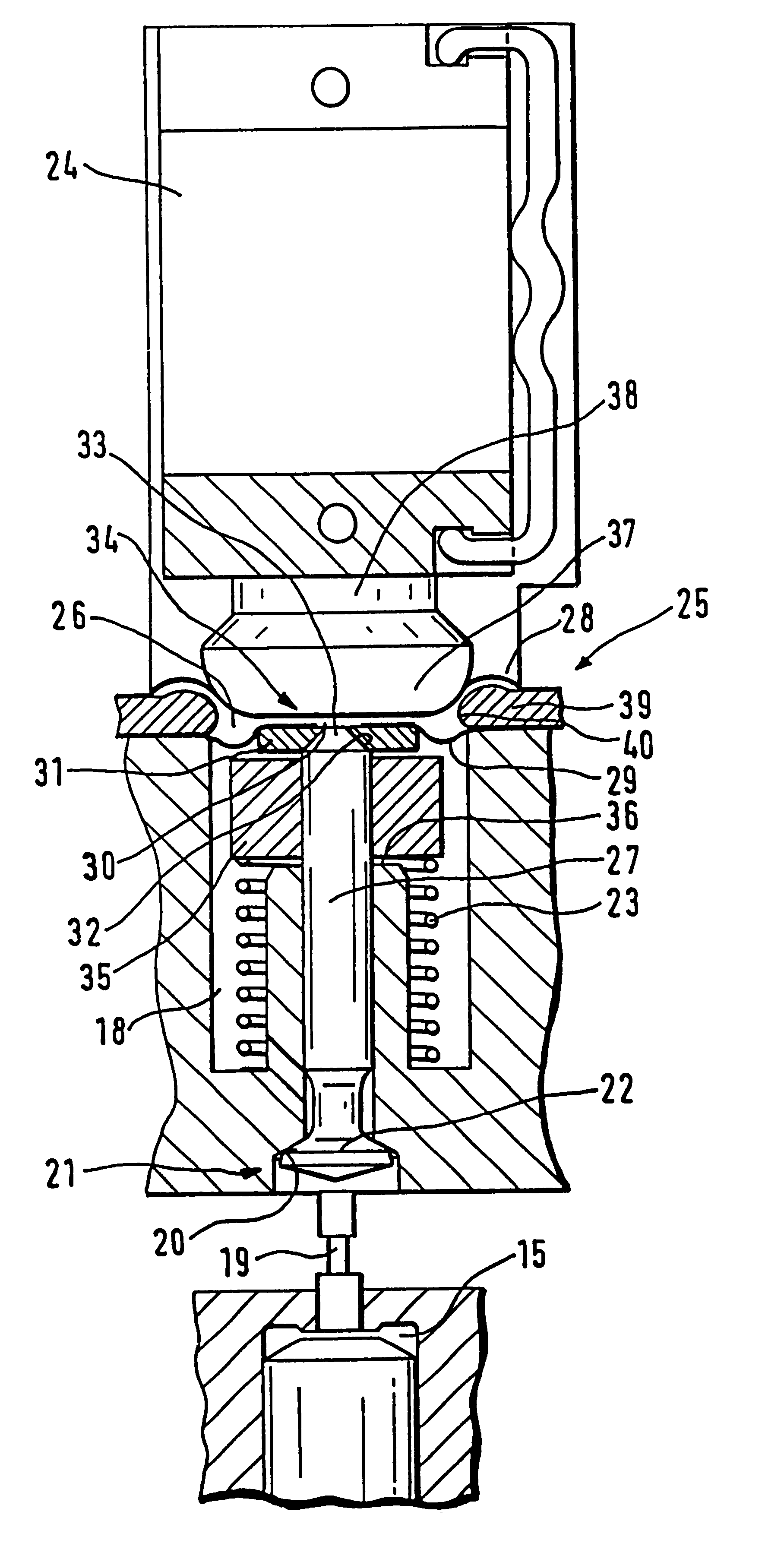
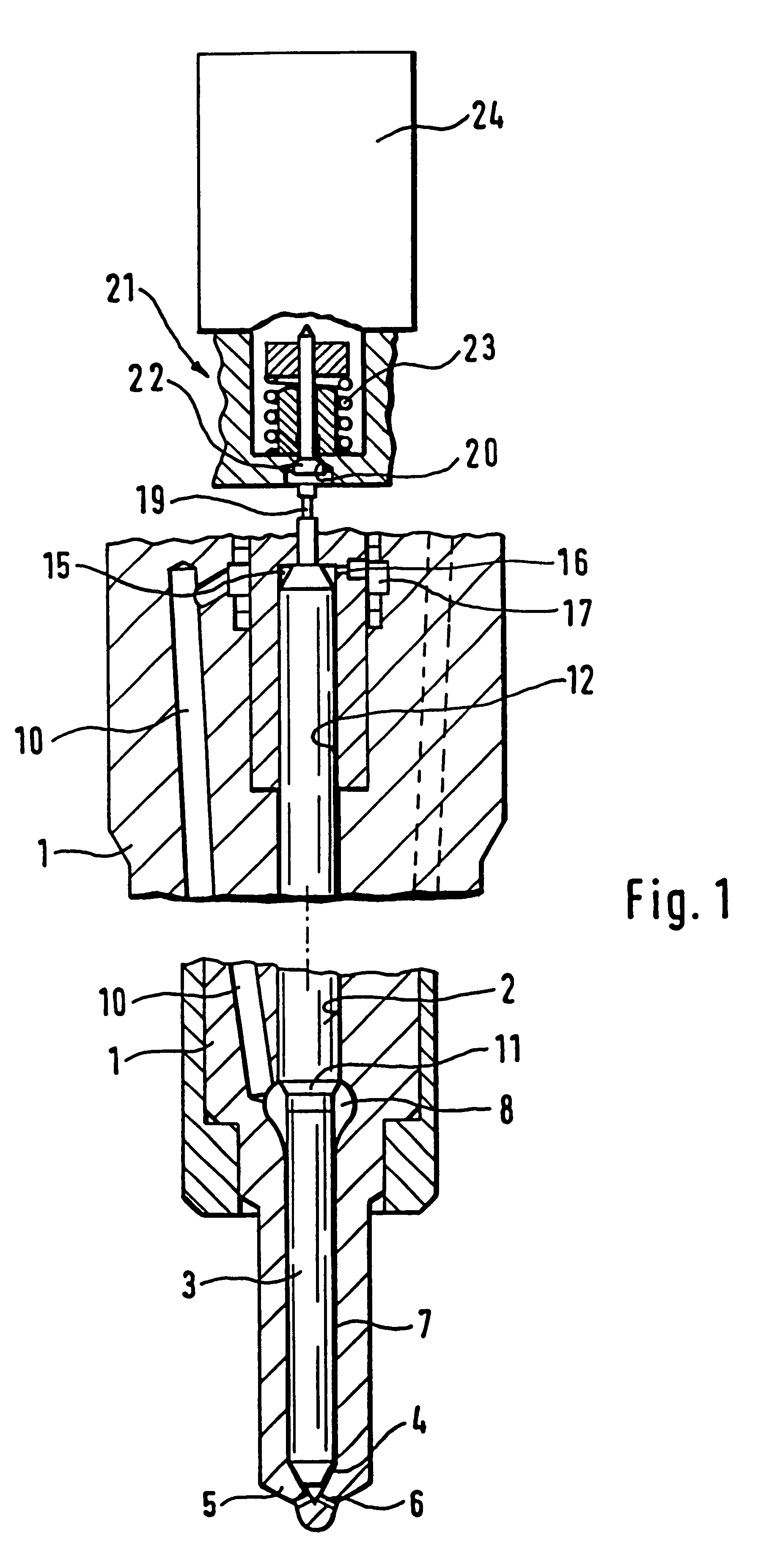
The valve according to the invention is used in a fuel injection valve, the essential parts of which are reproduced in the sectional view in FIG. 1. This injection valve has a valve housing 1 in which a valve needle 3 is guided in a longitudinal bore 2. On its one end, the valve needle is provided with a conical sealing face 4, which cooperates with a seat at the tip 5 of the valve housing protruding into the combustion chamber, and injection openings lead from this seat and connect the inside of the injection valve, in this instance, the annular chamber 7 that encompasses the valve needle 3 and is filled with fuel at injection pressure, with the combustion chamber in order to thus carry out an injection when the valve needle has lifted up from its seat. The annular chamber communicates with another pressure chamber 8, which continuously communicates with a pressure line 10, via which the fuel injection valve is supplied with fuel at injection pressure from a high-pressure fuel rese...


PUM


Abstract

A valve for controlling fluids, which in order to be actuated, cooperates with a fluid-filled membrane actuator. A coupling chamber provided in the membrane actuator is sealed by two membranes as dividing walls. In order to compensate for fluid losses produced by pressure acting on the membrane actuator, a filling valve is provided, which is disposed in the region of one of the two membranes. A refilling of the membrane actuator during the closed phase of the control valve is assured by way of the filling valve. A filling of this kind can also compensate for length changes of the piezoelectric actuator, the valve, or the valve housing. The valve is designated for use in fuel injection devices for internal combustion engines of motor vehicles.

Description

PRIOR ARTThe invention relates to a valve for controlling fluids EP 0 477 400 has disclosed a valve of this kind. There, the actuation piston of the valve member is disposed so that it can move in a sealed fashion in a smaller diameter part of a stepped bore, whereas a larger diameter piston that is moved with the piezoelectric actuator is disposed in a larger diameter part of the stepped bore. A hydraulic chamber is fixed between the two pistons in such a way that when the actuator moves the larger piston by a particular distance, the actuation piston of the valve member is moved by a distance that is enlarged by the transmission ratio of the stepped bore diameter. The valve member, the actuation piston, the larger diameter piston, and the piezoelectric actuator are disposed in succession on a common axis.With valves of this kind, there is the problem of compensating for length changes of the piezoelectric actuator, the valve, or the valve housing by means of the hydraulic coupling...

Claims


Application Information

Patent Timeline
Patent Type & Authority Patents(United States)
IPC IPC(8): F02M59/46F02M59/00F16K31/00F02M47/02H01L41/00H01L41/04F02M63/00F02M51/00F02M47/00F16K31/02
CPCF02M47/027F02M63/0026F02M63/0035F16K31/004F16K31/007H01L41/04F02M2200/706H10N30/80F02M59/46
Inventor POTSCHIN, ROGERBOECKING, FRIEDRICH
Owner ROBERT BOSCH GMBH
Why Eureka
Try Eureka