
Sensor for remote detection of objects

a technology for remote detection and objects, applied in the direction of mechanical actuation of burglar alarms, instruments, and reradiation, etc., can solve problems such as narrow shop exits, unfriendly customers, and former shoplifters

Inactive Publication Date: 2001-05-01
DEMODULATION
View PDF11 Cites 18 Cited by
  • Summary
  • Abstract
  • Description
  • Claims
  • Application Information

AI Technical Summary

Problems solved by technology

If an unauthorized person tries to remove the cassette upper portion, the disc will impact the fragile ink ampoule through the mounting pin, wherein the former will break or otherwise start leaking.
Strictly mechanical theft protections according to the above have a disadvantage in that even if a potential shoplifter may be discouraged from attempting to steal an article (since the article will possibly be destroyed, if the theft protection is removed), nothing stops the shoplifter from leaving the theft protection untampered on the article at the actual moment of theft and only later removing the theft protection at an undisturbed location other than the shop premises.
Since the detection is made by inductive means, antipilferage systems of this kind suffer from a short detection range of a few meters only, requiring the antipilferage arcs to be arranged close to each other and thereby making the shop exit narrow and "unfriendly" for the customers.
A drawback of such transponders is that they require a plurality of components as well as a considerable space and a high price per unit.

Method used


Image

  • Sensor for remote detection of objects
  • Sensor for remote detection of objects
  • Sensor for remote detection of objects

Examples


Embodiment Construction

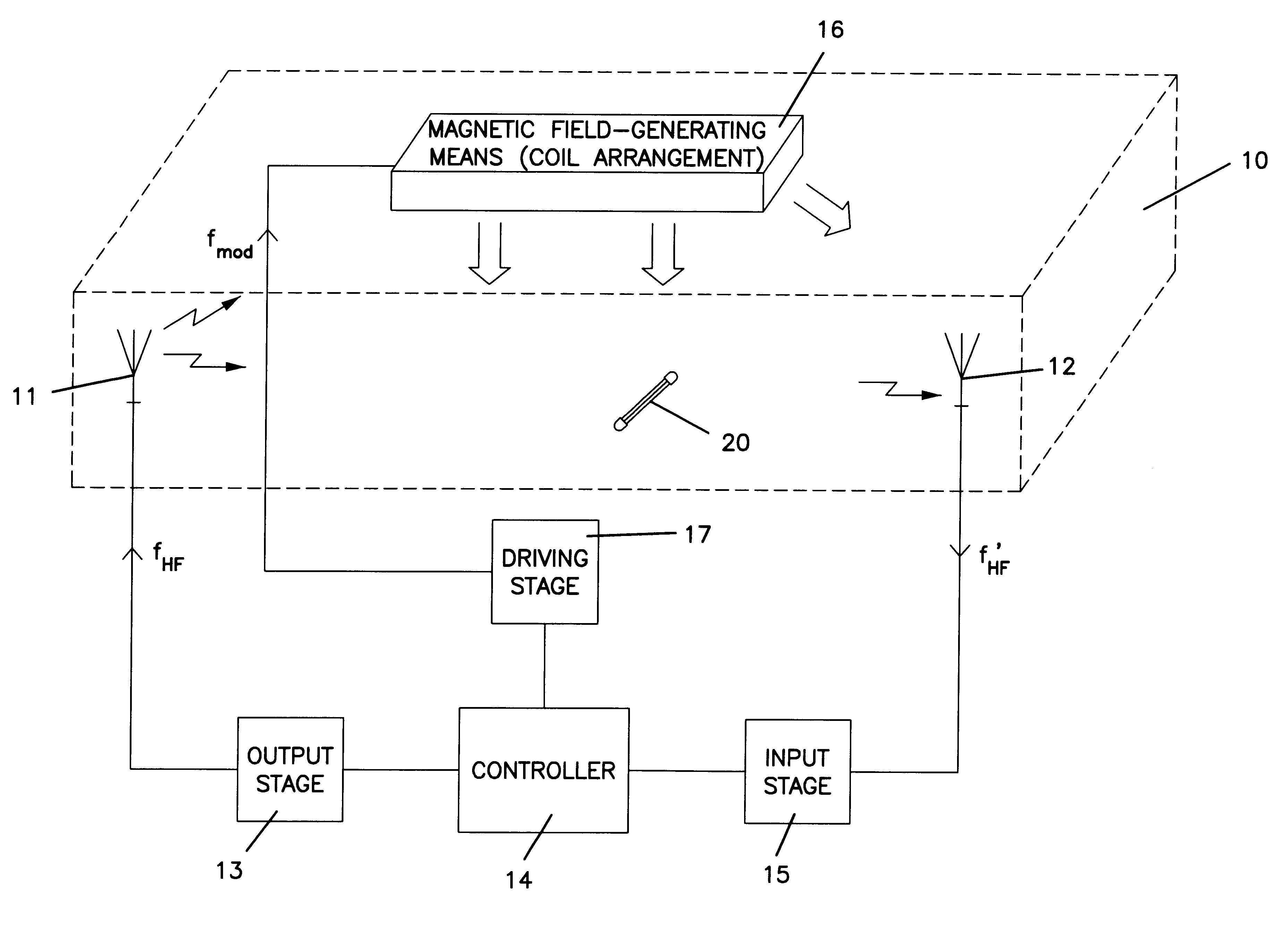
In FIG. 1 an antipilferage system is illustrated, wherein the sensor according to the present invention may be applied. A transmitter antenna 11 and a receiver antenna 12 are arranged in a surveillance or monitoring zone 10. The transmitter antenna 11 is operatively connected to an output stage 13, which in turn is connected to a controller 14. The output stage 13 comprises various conventional driving and amplifying circuits as well as means for generating a high-frequency electric current i.sub.HF, which will alternately run back and forth through the transmitter antenna 11 when supplied thereto, thereby generating a high-frequency electromagnetic field at a frequency f.sub.HF around the transmitter antenna. As will be described in more detail below, this electromagnetic field is used for exciting a transponder or sensor 20 present in the surveillance zone 10, said transponder or sensor transmitting an electromagnetic reply signal to be received by the receiver antenna 12, in resp...


PUM


Abstract

A sensor for remote detection of objects in a surveillance zone (10) is preferably intended to be used in an article surveillance zone, which further has at least one transmitter means (11, 13) and at least one receiver means (12, 15) for transmitting and receiving, respectively, electromagnetic radio-frequency signals in the surveillance zone, and at least one modulating means (16) for generating a modulation field in the surveillance zone. The sensor is arranged to transmit an electromagnetic reply signal at the reception of electromagnetic energy from the transmitter means, said reply signal being dependent on the modulation field and being receivable by the receiver means. A magnetic element (23) is arranged in a sensor body (21; 101, 102), the magnetic properties of the element being controllable by a magnetic field acting as the modulation field, wherein the amplitude of the reply signal from the sensor is controllable through the magnetic modulation field.

Description

The present invention relates to a sensor for remote detection of objects in a surveillance zone, preferably for use in an article surveillance system, which further comprises at least one transmitter means and at least one receiver means for transmitting and receiving, respectively, electromagnetic radio-frequency signals in the surveillance zone, and at least one modulating means for generating a modulation field in the surveillance zone, said sensor being arranged to transmit an electromagnetic reply signal at the reception of electromagnetic energy from said transmitter means, and said reply signal being dependent on said modulation field and being receivable by said receiver means.DESCRIPTION OF THE PRIOR ARTFor many years now a large demand for simple and still reliable surveillance systems for monitoring objects or articles within a given area has been noticed in various business and industrial applications. A common example is shop antipilferage systems, which are available ...

Claims


Application Information

Patent Timeline
IPC IPC(8): G01V15/00G08B13/24G01V3/08
CPCG01V15/00G08B13/2442G08B13/2445G08B13/2471G08B13/2485
Inventor TYREN, CARLQUINONES, CHRISTIAN
Owner DEMODULATION
Learn More