Apparatus and methods for determining the three-dimensional shape of an object using active illumination and relative blurring in two images due to defocus

a technology of three-dimensional shape and object, applied in the field of three-dimensional structure or object mapping from two-dimensional images, can solve the problem that the recovery of three-dimensional measurements of a structure, still under investigation, cannot serve as stand-alone approaches

Inactive Publication Date: 2001-05-08
THE TRUSTEES OF COLUMBIA UNIV IN THE CITY OF NEW YORK
View PDF9 Cites 720 Cited by
  • Summary
  • Abstract
  • Description
  • Claims
  • Application Information

AI Technical Summary

Problems solved by technology

A pertinent problem in computational vision is the recovery of three-dimensional measurements of a structure from two-dimensional images.
Such techniques are still under investigation and it is expected they will prove complementary to other techniques but cannot serve as stand-alone approaches.
The primary problem encountered by these methods has proved to be correspondence and feature tracking.
In addition, passive algorithms have yet to demonstrate the accuracy and robustness required for high-level perception tasks such as object recognition and pose estimation.
However, it has suffered from one inherent drawback, namely, speed.
However, differences between the two images tend to be very subtle and previous solutions to depth from defocus have met with limited success as they are based on rough approximations to the optical and sensing mechanisms involved in focus analysis.
The result is a blurred image of P. It is clear that a single image does not include sufficient information for depth estimation as two scenes defocused to different degrees can produce identical image elements.
Simple as this procedure may appear, several technical problems emerge when implementing a method of practical value.
First, there is the problem of determining relative defocus.
Since the effect of blurring is frequency dependent, it is not meaningful to investigate the net blurring of the entire collection of frequencies that constitute scene texture.
Given that the dominant frequencies of the scene are unknown and possibly spatially varying, one is forced to use complex filtering techniques that add to the complexity of the process.
This complexity makes the

Method used


Image

  • Apparatus and methods for determining the three-dimensional shape of an object using active illumination and relative blurring in two images due to defocus
  • Apparatus and methods for determining the three-dimensional shape of an object using active illumination and relative blurring in two images due to defocus
  • Apparatus and methods for determining the three-dimensional shape of an object using active illumination and relative blurring in two images due to defocus

Examples


Embodiment Construction

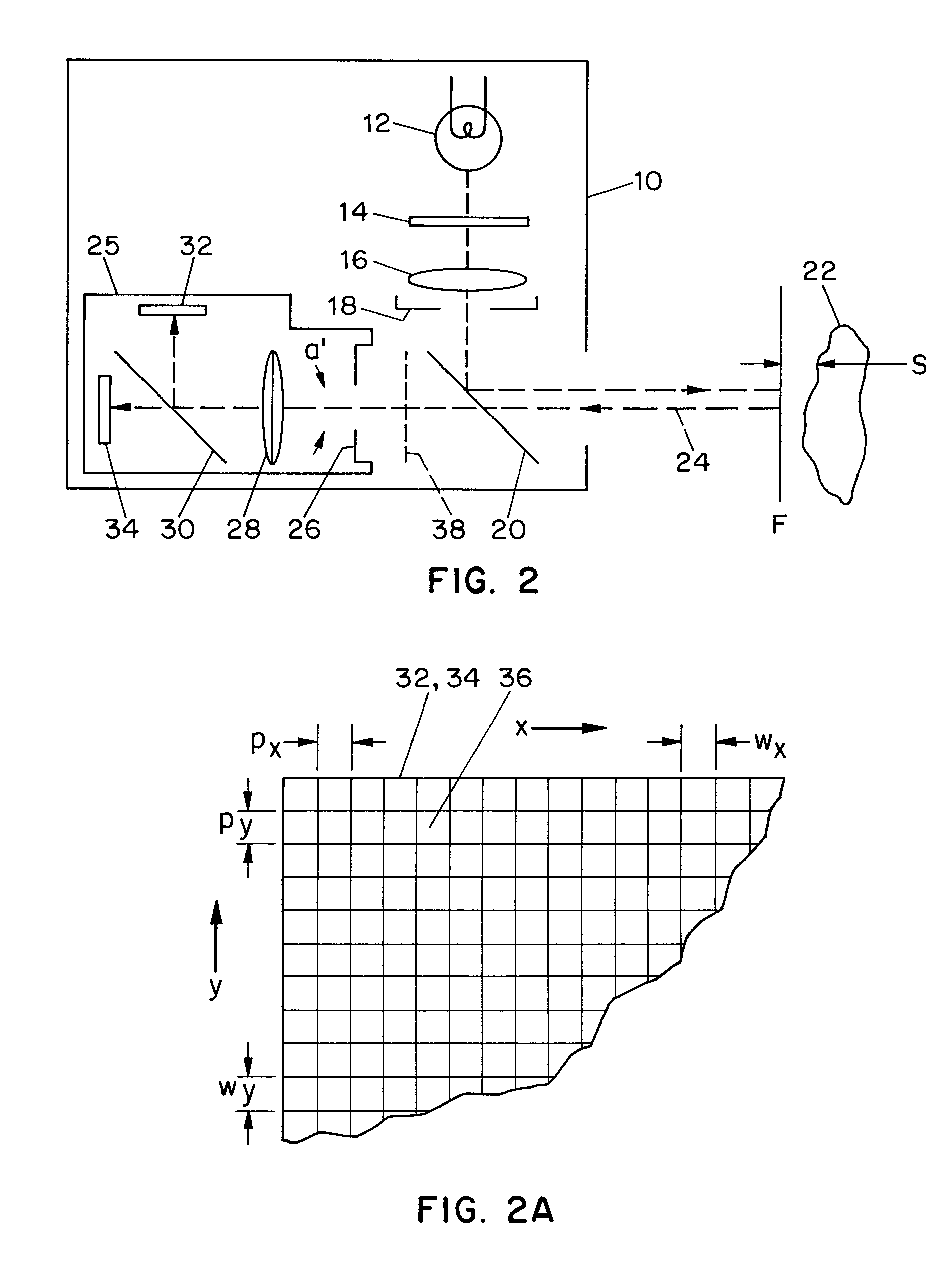
One variation of the sensor 10 addresses the fact that the defocus effect is a function of the chromatic content of the illuminating light. Most lenses have slightly different focal length for-different light wavelengths, accordingly, the accuracy of determination of depth from defocus can vary with the spectral characteristics of the illumination and the color of the reflecting surface of the object, since depth determination relies on prior knowledge of the focal length f of lens 28. This source of error can be avoided by providing a spectral band-pass filter 38, shown in FIG. 2, to allow only certain elements of reflected light to be imaged. A band-pass filter would limit the range of the wavelengths to be imaged and thereby limit the chromatic variation in the focal length of the lens. Other possible locations for such a filter are shown in FIG. 8 at 38', 38" and 38'".

In the case where the illumination source 12 is a laser, the filter is preferably narrow band, passing the laser...


PUM


Abstract

A method and apparatus for mapping depth of an object (22) in a preferred arrangement uses a projected light pattern to provide a selected texture to the object (22) along the optical axis (24) of observation. An imaging system senses (32, 34) first and second images of the object (22) with the projected light pattern and compares the defocused of the projected pattern in the images to determine relative depth of elemental portions of the object (22).

Description

I. Field of the InventionThe present invention relates to techniques for mapping a three-dimensional structure or object from two-dimensional images, and more particularly relates to techniques employing active illumination to retrieve depth information.II. Description of the Related ArtA pertinent problem in computational vision is the recovery of three-dimensional measurements of a structure from two-dimensional images. There have been many proposed solutions to this problem that can be broadly classified into two categories; passive and active. Passive techniques such as shape from shading and texture attempt to extract structure from a single image. Such techniques are still under investigation and it is expected they will prove complementary to other techniques but cannot serve as stand-alone approaches. Other passive methods, such as stereo and structure from motion, use multiple views to resolve shape ambiguities inherent in a single image. The primary problem encountered by ...

Claims


Application Information

Patent Timeline
IPC IPC(8): G06T7/00G01C3/06G01B11/24G02B27/22G06T1/00G06V10/145
CPCG02B27/2278G06K9/2036G06T7/0069G01C3/32G06T7/571H04N13/271H04N13/236G02B30/52G06V10/145G06V20/66
Inventor NAYAR, SHREENOGUCHI, MINORIWANTANABE, MASAHIRO
Owner THE TRUSTEES OF COLUMBIA UNIV IN THE CITY OF NEW YORK
Why Eureka
Try Eureka