Vacuum generating apparatus with multiple rotors

a vacuum cleaner and generating apparatus technology, applied in the direction of positive displacement liquid engines, piston pumps, liquid fuel engines, etc., can solve the problems of reducing the output efficiency, reducing the size, and affecting the efficiency of the outpu

Inactive Publication Date: 2001-05-15
AMOTECH
View PDF9 Cites 85 Cited by
  • Summary
  • Abstract
  • Description
  • Claims
  • Application Information

AI Technical Summary

Problems solved by technology

However, such reduction in size has confronted to a saturated state due to limitation of lengthy direction of a motor being an essential component in a vacuum cleaner.
In particular, in the case of an upright type of a vacuum cleaner, a big load is applied to hands during cleaning, to thereby cause much fatigue and inconvenience a user due to a large volume.
Also, an air guide mechanism from sucking to discharging is formed by the impeller along the axial direction of the motor, which is not so simple that an output efficiency is lowered.
Also, an air guide vane 21 is essentially required for guiding air from the imp

Method used


Image

  • Vacuum generating apparatus with multiple rotors
  • Vacuum generating apparatus with multiple rotors
  • Vacuum generating apparatus with multiple rotors

Examples


first embodiment

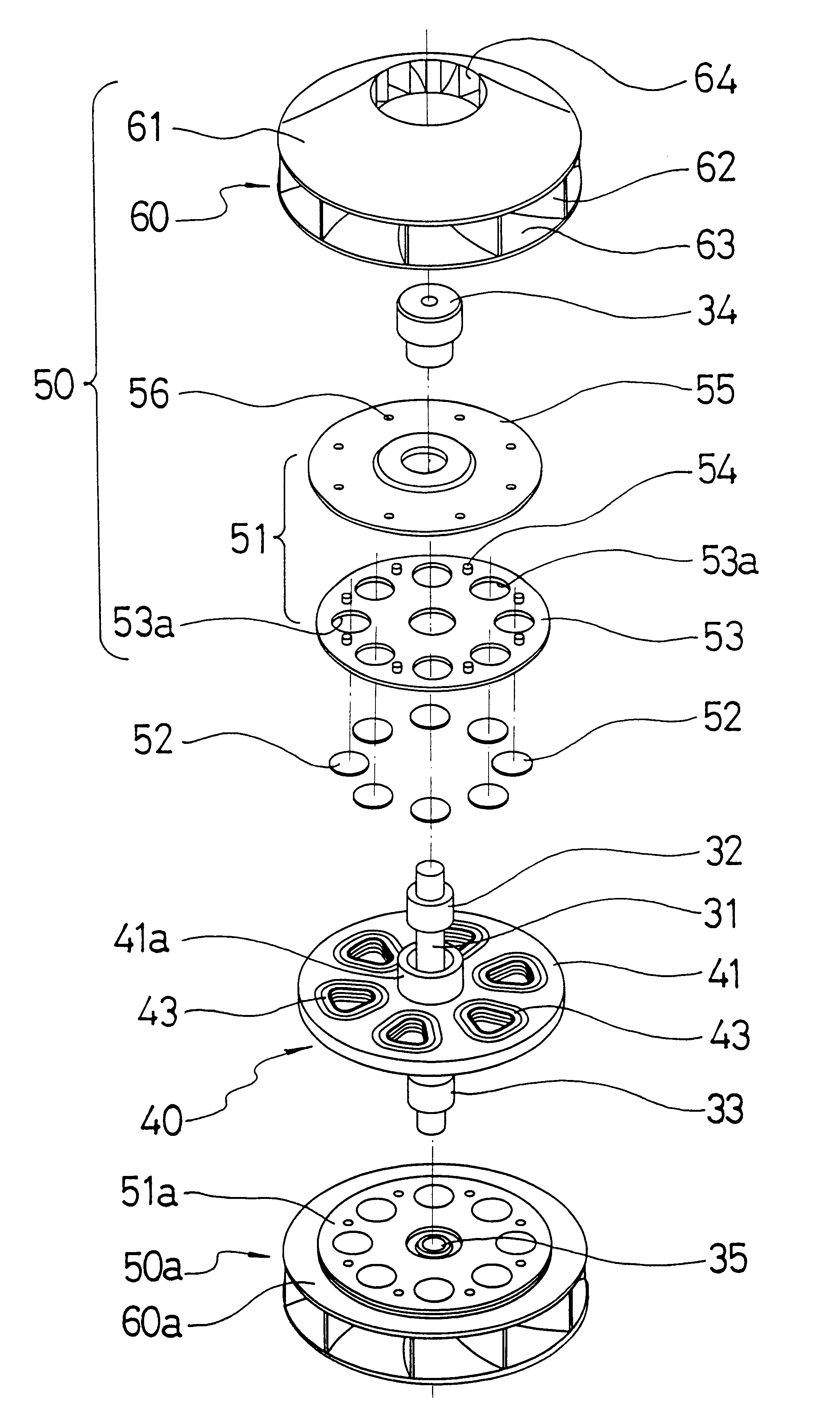
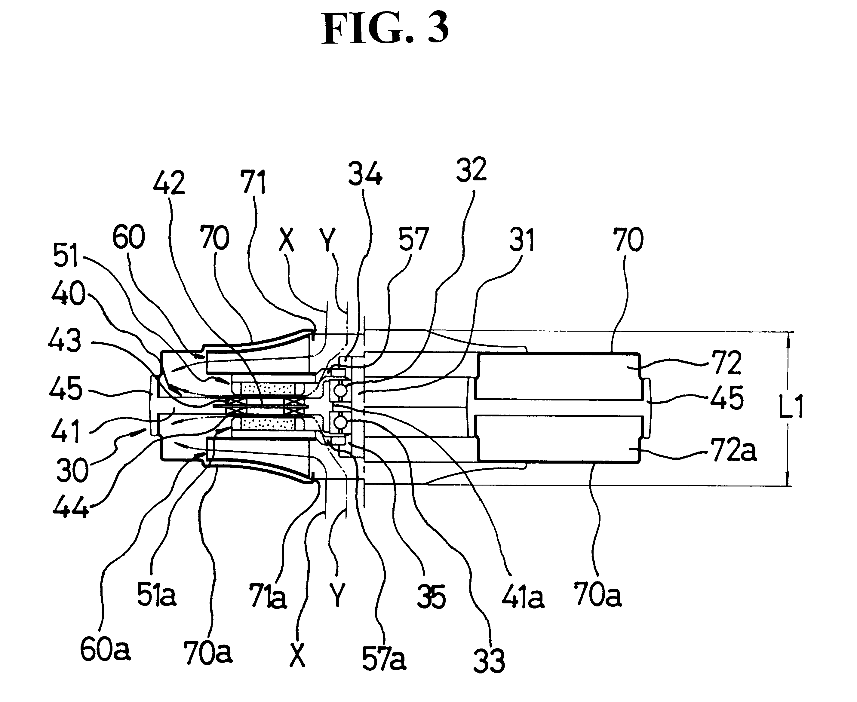
First, referring to FIGS. 3 and 4, a vacuum generating apparatus for a double impeller type vacuum cleaner according to the present invention uses a double rotor type motor as a basic structure among axial type coreless brushless DC motors which have been disclosed in the U.S. patent application Ser. No. 08 / 783,908 which was granted and whose issue fees were paid on Apr. 7, 1999 by the same applicant and modifies the double rotor type motor so as to be suitable for power source of the vacuum cleaner for generating a rotating force.

The vacuum generating apparatus of the present invention which including a modified motor 30 includes a single stator 40 located at the center, upper and lower rotors 51 and 51a which are fixed by bushings 34 and 35 to either end of a rotating shaft 31 which is rotatably supported in the stator 40 and disposed at the upper and lower sides of the stator 40, respectively, upper and lower impellers 60 and 60a which are fixed to the upper and lower rotors 51 a...

second embodiment

The second embodiment adopts a single-impeller type differently from the first embodiment of the double-impeller type. In FIGS. 6 and 7, the same reference numerals are assigned to the same portions as those of FIGS. 3 through 5. Thus, the detailed description thereof will be omitted.

First, the motor 30 uses the same double rotor type coreless brushless DC motor as that of the fist embodiment, in which the single impeller 60 is installed in only the upper rotor 51, not in the lower rotor 51a.

Thus, the outer circumferential portion of the stator supporter 41b is not extended long as in the first embodiment in order to secure an inner space between the upper and lower housings 70 and 73, but a number of bosses 46 for combination with the lower housing 73 protrude toward the bottom surface. The stator supporter 41b is fixed to the lower housing 73 in which a fixing bolt 74 is engaged with the boss 46.

In this case, as the rotors 51 and 51a rotate, the impeller 60 rotates. As a result, t...


PUM


Abstract

A vacuum generating apparatus for a vacuum cleaner is provided, in which an axial type coreless brushless direct-current (DC) motor is implemented in the form of a rotor-impeller integration structure. The vacuum generating apparatus includes an axial type brushless DC motor in which disc-shaped upper and lower rotors are symmetrically disposed facing the upper and lower portions of a disc-shaped stator at either end of a rotating shaft rotatably supported in the inner circumferential portion of the stator, upper and lower impellers integrally fixed in the upper and lower rotors, respectively, and upper and lower housings whose outer circumferential portions are combined with the outer circumferential portions of the respective disc-shaped stator such that air sucked via sucking inlets formed at the center of the housings is guided to a discharging outlet together with the stator. A single rotor structure can also be adopted.

Description

1. Field of the InventionThe present invention relates to a vacuum generating apparatus for a vacuum cleaner, and more particularly, to a vacuum generating apparatus for a vacuum cleaner in which an axial type coreless brushless direct-current (DC) motor is implemented in the form of a rotor-impeller integration structure, to thereby realize ultra-compactness, thinness, light-weight, low-noise, long lifetime, non-existence of carbon dust, and improved productivity.2. Description of the Related ArtIn accordance with development of electronics industry, a vacuum cleaner has become more compact, thinner and lighter. However, such reduction in size has confronted to a saturated state due to limitation of lengthy direction of a motor being an essential component in a vacuum cleaner.In general, as the type of a vacuum cleaner, there are a traditional type as shown in FIG. 1, and an upright type and a canister type both of which are adopted in Europe. In all types of vacuum cleaners, compa...

Claims


Application Information

Patent Timeline
IPC IPC(8): F04D25/16F04D25/06F04D25/00F04D25/02F04D29/44H02K7/14H02K21/12H02K21/24A47L9/00H02K16/02
CPCF04D25/0653F04D25/166F04D29/441H02K7/14H02K21/24
Inventor KIM, BYUNG KYUKIM, JOON
Owner AMOTECH
Why Eureka
Try Eureka