
Data input device

a data input and data technology, applied in the direction of mechanical pattern conversion, instruments, cathode-ray tube indicators, etc., can solve the problems of large desk space occupied by full-size keyboards used with desktop computers, large volume, and inconvenient us

Inactive Publication Date: 2001-05-15
GOLDMAN ALFRED
View PDF15 Cites 81 Cited by
  • Summary
  • Abstract
  • Description
  • Claims
  • Application Information

AI Technical Summary

Problems solved by technology

These keyboards typically are large and bulky, and their use can thus be awkward, especially if there is a limited amount of space available for using the keyboard.
In particular, full-size keyboards used with a desktop computer take up a large amount of desk space which could be used for other purposes.
Such large keyboards have also been cited as the cause of certain hand or arm muscular problems, such as carpal tunnel syndrome.
As such keyboards include within them various electrical components for transmitting the keystroke signals to the computer, should the user spill liquid or deposit other foreign substances onto the keyboard, a malfunction of the keyboard is likely to result.
This device, however, is unable to perform all of the operations of a conventional keyboard, requires knowledge of another language, sign language, to operate it, and cannot be used in any way other than translating sign language into computer readable form.
However, the bulky electrical components of these keyboards limit how small and light-weight these keyboards may be.
Although a keyboard or other data entry device may be temporarily removed from a workspace to create additional workspace, this option is not available for portable laptop computers with their attached keyboards.
In fact, the size of a keyboard for a laptop computer or computer notebook is often one of the main size limiting factors for the device.

Method used


Image

  • Data input device
  • Data input device
  • Data input device

Examples


Embodiment Construction

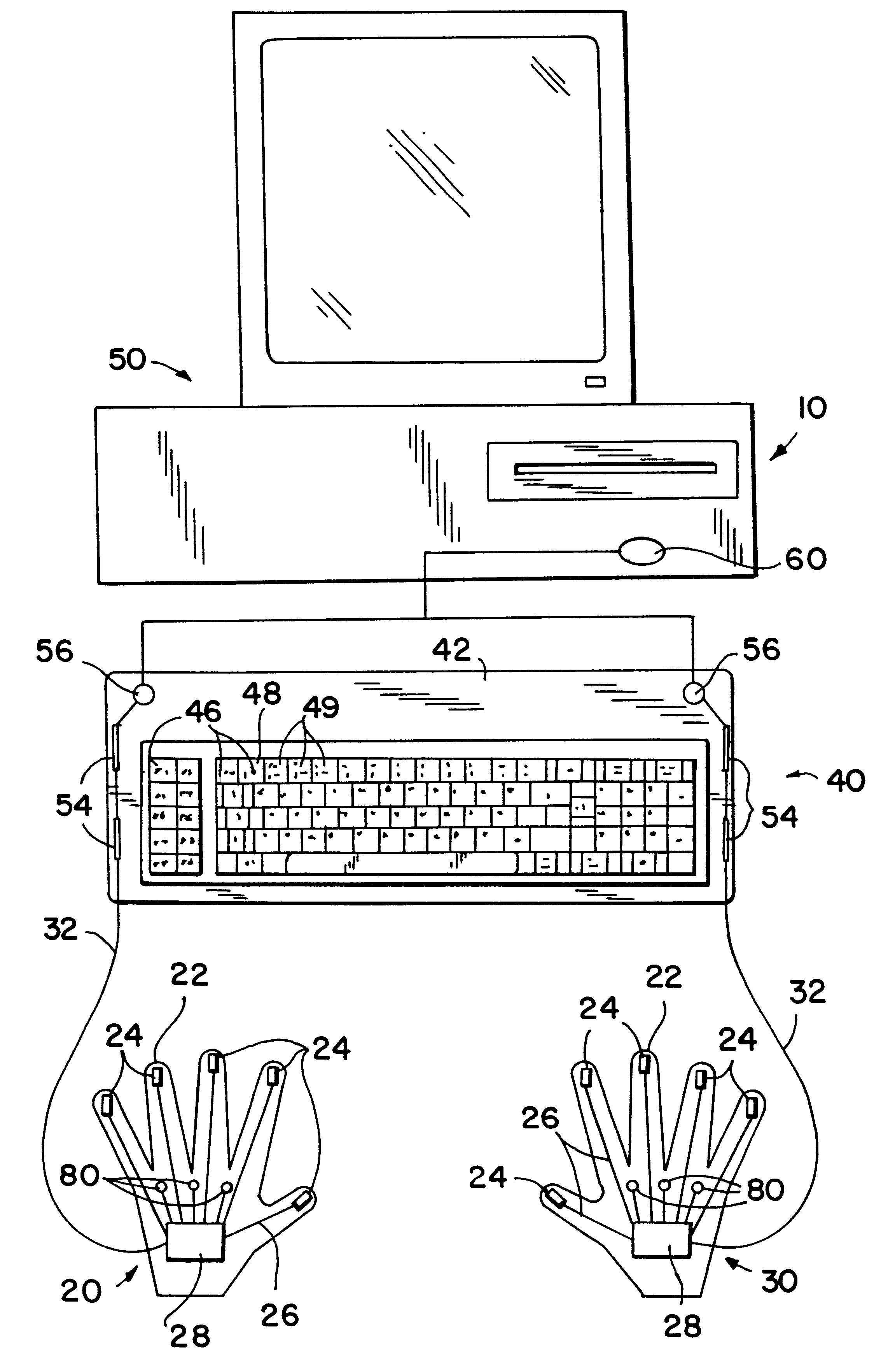
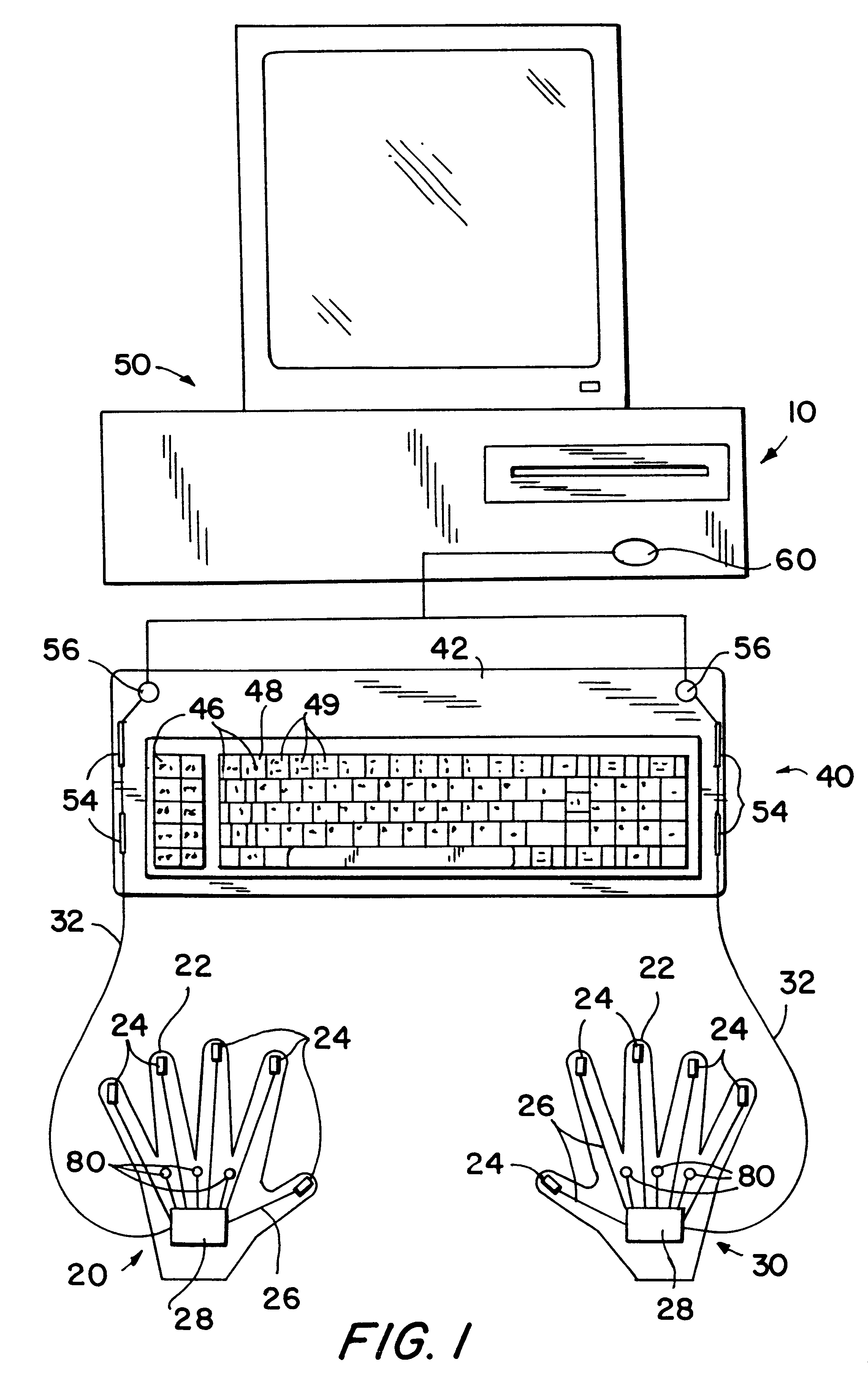
FIG. 1 shows a first embodiment of a data entry system 10 employing the data entry device of the present invention. The system 10 includes a pair of gloves 20, 30, respectively, a keypad 40 and a computer 50. Each glove 20, 30 is identical, except that one glove 20 is designed to be worn on the left hand and the other glove 30 on the right hand. Although two gloves are shown, alternatively only one glove may be required for a particular type of data entry keypad 40. Each glove 20, 30 has five digits 22, each accommodating a respective finger of a user. At the tip of each digit 22 of the gloves 20, 30 is securely mounted a sensing device 24. Although each glove 20, 30 is shown as having five digits, alternatively one or both gloves may have less than five digits, and thus less than five sensing devices 24, depending on the particular keypad 40 to be used. Additionally, the gloves 20, 30 need not cover the entire hand of the user but only a sufficient portion thereof so that there is ...


PUM


Abstract

A data entry device, including a plurality of sensing devices worn on a user's fingers, and a flat light-weight keypad for transmitting signals indicative of data entry keyboard functions to a computer or other data entry device. The sensing devices include sensors are used to detect unique codes appearing on the keys of the keypad or to detect a signal, such as a radar signal, generated by the signal generating device mounted to the keypad. Alternatively, sensing devices may be mounted to the keypad to determine the location of a user's finger upon selection of a keypad key. Pressure sensitive switches, one associated with each finger contain resistive elements and optionally sound generating means and are electrically connected to the sensors so that when the switches are pressed they activate a respective sensor and also provide a resistive force and sound comparable to keys of a conventional keyboard. Alternatively, a flat fully functional keyboard or touchscreen, which does not provide the user with significant tactile or auditory indication of a user's selection of a key, can be used and pressure sensitive switches containing resistive elements and optionally sound generating means are mounted to the user's fingers.

Description

1. Field of the InventionThe present invention relates to a device for entering data or signals to an electronic device, such as a computer, telephone, electronic game, cash register, electronic musical keyboard or other electronic device having a data entry keyboard.2. Description of the Related ArtThere are many known types of keyboards used for inputting keystrokes and various other commands and data to electronic devices. These keyboards typically are large and bulky, and their use can thus be awkward, especially if there is a limited amount of space available for using the keyboard. In particular, full-size keyboards used with a desktop computer take up a large amount of desk space which could be used for other purposes. Such large keyboards have also been cited as the cause of certain hand or arm muscular problems, such as carpal tunnel syndrome. As such keyboards include within them various electrical components for transmitting the keystroke signals to the computer, should t...

Claims


Application Information

Patent Timeline
IPC IPC(8): G06F3/00G06F3/01
CPCG06F3/011
Inventor GOLDMAN, ALFRED
Owner GOLDMAN ALFRED
Learn More