Steel fiber for reinforcement of high-performance concrete

a technology of high-performance concrete and steel fiber, which is applied in the directions of yarn, textiles and paper, transportation and packaging, etc., can solve the problem that anchorages with smaller dimensions do not work to the same degr

Inactive Publication Date: 2001-05-22
NV BEKAERT SA
View PDF16 Cites 53 Cited by
  • Summary
  • Abstract
  • Description
  • Claims
  • Application Information

AI Technical Summary

Problems solved by technology

Anchorages with smaller dimensions will not work to the same degree, since they would not bridge adequately the interfacial zone.

Method used


Image

  • Steel fiber for reinforcement of high-performance concrete
  • Steel fiber for reinforcement of high-performance concrete
  • Steel fiber for reinforcement of high-performance concrete

Examples


first preferable embodiment

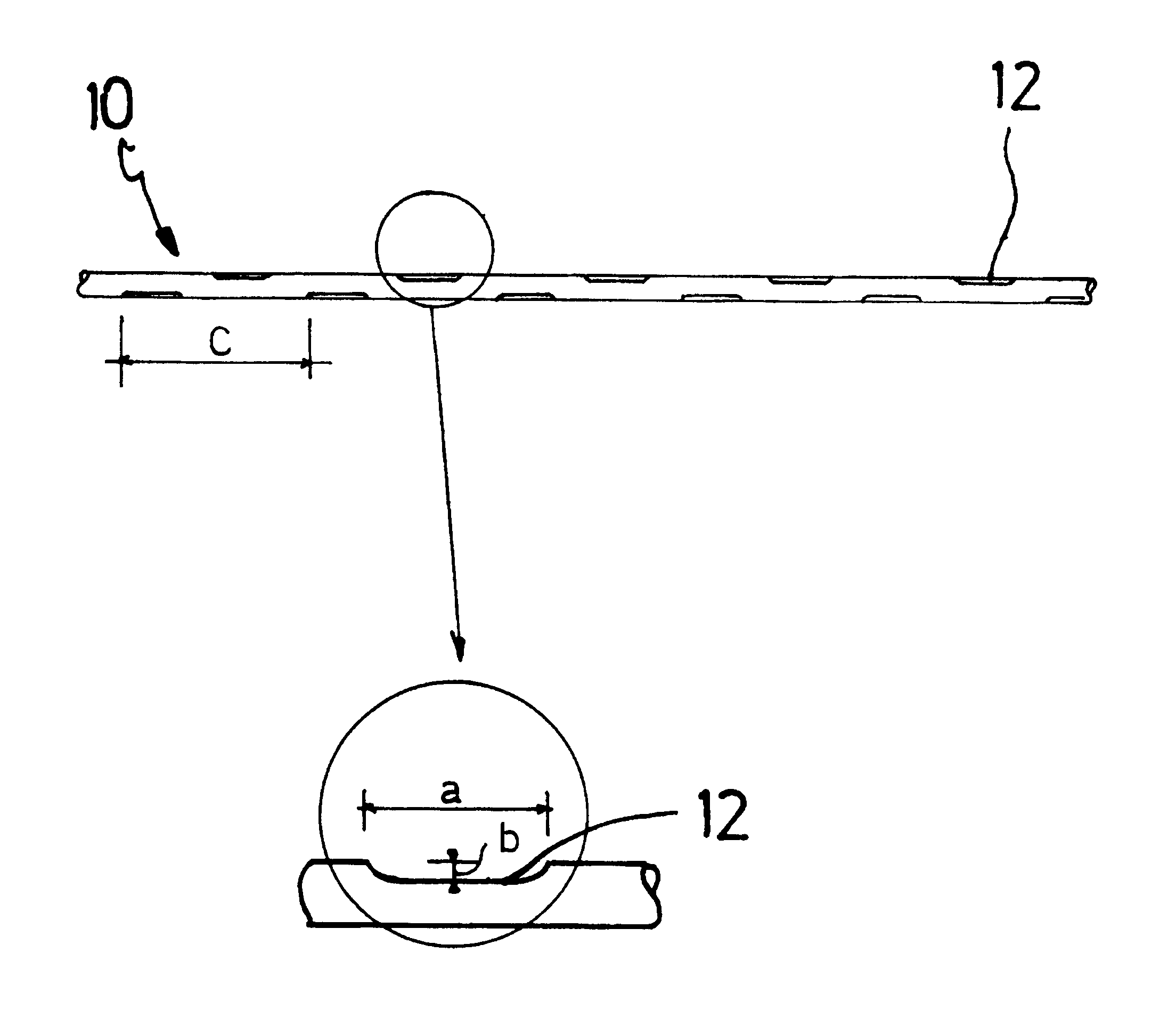
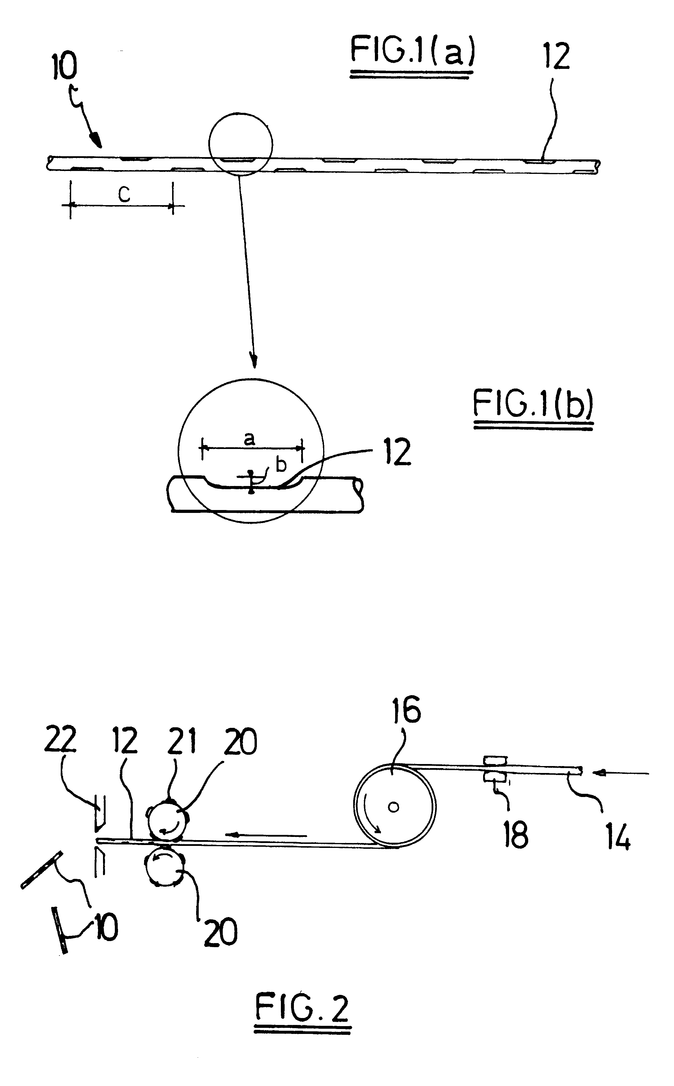
FIG. 1(a) shows a steel fiber 10 which is provided with indentations 12 which are regularly distributed along its length. FIG. 1(b) illustrates in more detail an indentation 12. For example, the steel fiber 10 has a length of 13 mm, and--apart from the indentations 12--a round cross-section with a diameter of 0.20 mm. The size a of an indentation 12 in the longitudinal direction is 0.50 mm and the depth b of an indentation 12 is 0.010 mm (=10 .mu.m). The indentations 12 are provided both at the upper side and at the under side of the steel fiber 10. The distance (pitch) between two indentations at the upper or at the under side is about 1.50 mm.

FIG. 2 illustrates how a steel fiber 10 with indentations 12 can be manufactured. A steel wire 14 is drawn by means of a winding drum 16 through a (final) reduction die 18. Having reached its final diameter the wire 14 is further guided to two wheels 20 which are both provided at their surface with protrusions 21 in order to form the indentat...

second preferable embodiment

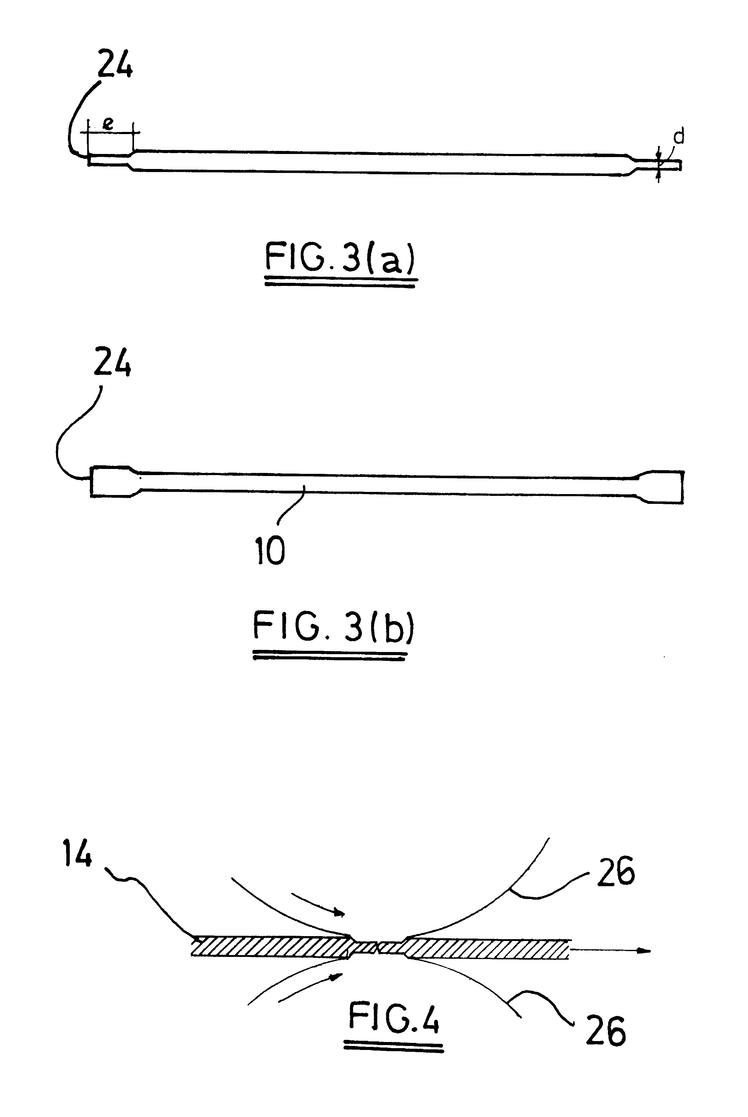
FIGS. 3(a) and 3(b) illustrate a straight steel fiber 10 with flattened ends 24. The flattened ends 24 provide the anchorage in the high-performance concrete. Preferably the steel fiber 10 has no burrs since burrs could provoke concentrations of tensions in the concrete and these concentrations could lead to initiation of cracks. The transition in the steel fiber 10 from the round transversal cross-section to the flattened ends 24 should not be abrupt but should be gradually and smooth. As an example the steel fiber 10 has following dimensions: a length of 13 mm, a diameter of a round cross-section of 0.20 mm, a thickness d of the flattened ends 24 of 0.15 mm and a length e of the flattened ends 24--transition zone included--of 1.0 mm.

FIG. 4 illustrates how a steel fiber 10 with flattened ends 24 can be manufactured by means of two rolls 26 which give flattenings to a steel wire 14 and simultaneously cut the steel wire into separate steel fibers.

Since a steel fiber 10 according to t...


PUM

PropertyMeasurementUnit
compressive strengthaaaaaaaaaa
lengthaaaaaaaaaa
thicknessaaaaaaaaaa

Abstract

A steel fiber (10) for reinforcement of high-performance concrete or mortar has a length ranging from 3 mm to 30 mm, a thickness ranging from 0.08 mm to 0.30 mm, and a tensile strength greater than 2000 MPa. The steel fiber is provided with anchorages (12,24) the dimension of which in a direction perpendicular to the longitudinal axis of the steel fiber is maximum 50% of the thickness. These anchorages provide an effective staying in the high-performance concrete without influencing the mixability of the steel fibers in a negative way.

Description

The invention relates to a straight steel fiber for reinforcement of high-performance concrete or mortar.BACKGROUND OF THE INVENTION.It is known in the art to reinforce high-performance concretes by means of steel fibers.BE-A3-1005815 (N.V. BEKAERT S.A.) teaches that for conventional concretes with a compressive strength ranging from 30 MPa to 50 MPa, it makes no sense to increase the tensile strength of a steel fiber above 1300 MPa since an increase in tensile strength does not add any increase in flexural strength to the reinforced concrete. BE 1005815 further teaches, however, that for concretes with an increased compressive strength, the tensile strength of the steel fibers should increase proportionally.WO-A1-95 / 01316 (BOUYGUES) adapts the average length of metal fibers to the maximum size of granular elements which are present in high-performance concrete so that metal fibers act as conventional rebars in high-performance concrete. The volume percentage of metal fibers in high...

Claims


Application Information

Patent Timeline
Patent Type & Authority Patents(United States)
IPC IPC(8): E04C5/01
CPCE04C5/012Y10T428/1241Y10T428/2978Y10T428/2976
Inventor LAMBRECHTS, ANN
Owner NV BEKAERT SA
Why Eureka
Try Eureka